Product List
اتصل بنا
البريد الإلكتروني: qiao@hvtest.cc
الجوال: +8615871365102
ما هو التطبيق: +8615871365102
-
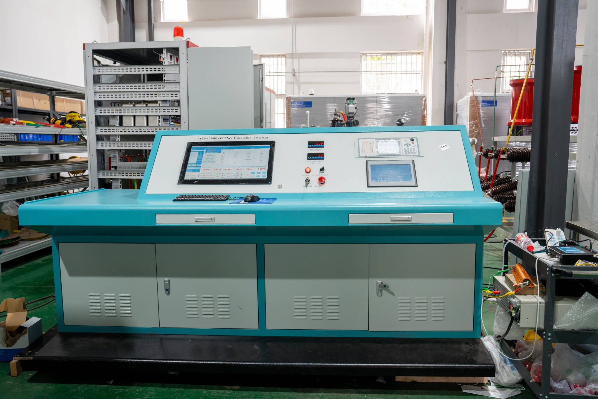
Transformer comprehensive test bench: Why is the "heart" of precise testing so important?
2026-02-05Have you ever been curious about the rigorous tests that the indispensable source of electricity in our daily lives has undergone? Today, we will talk about a crucial equipment - the transformer comprehensive test bench. It is like a "health center" for transformers, ensuring that each transformer can safely and efficiently deliver electricity to us.What is a transformer comprehensive test bench?Simply put, the transformer comprehensive test bench is an automated equipment that integrates multiple testing functions and can perform comprehensive performance testing on transformers. It is not a single instrument, but a system that can simulate various operating conditions, detect key indicators such as insulation performance, temperature rise characteristics, loss parameters, and short-circuit impedance of transformers. Only by passing this rigorous exam can transformers be allowed to work on the job.Factors affecting the comprehensive test of transformersStability of testing environment
أكثر -
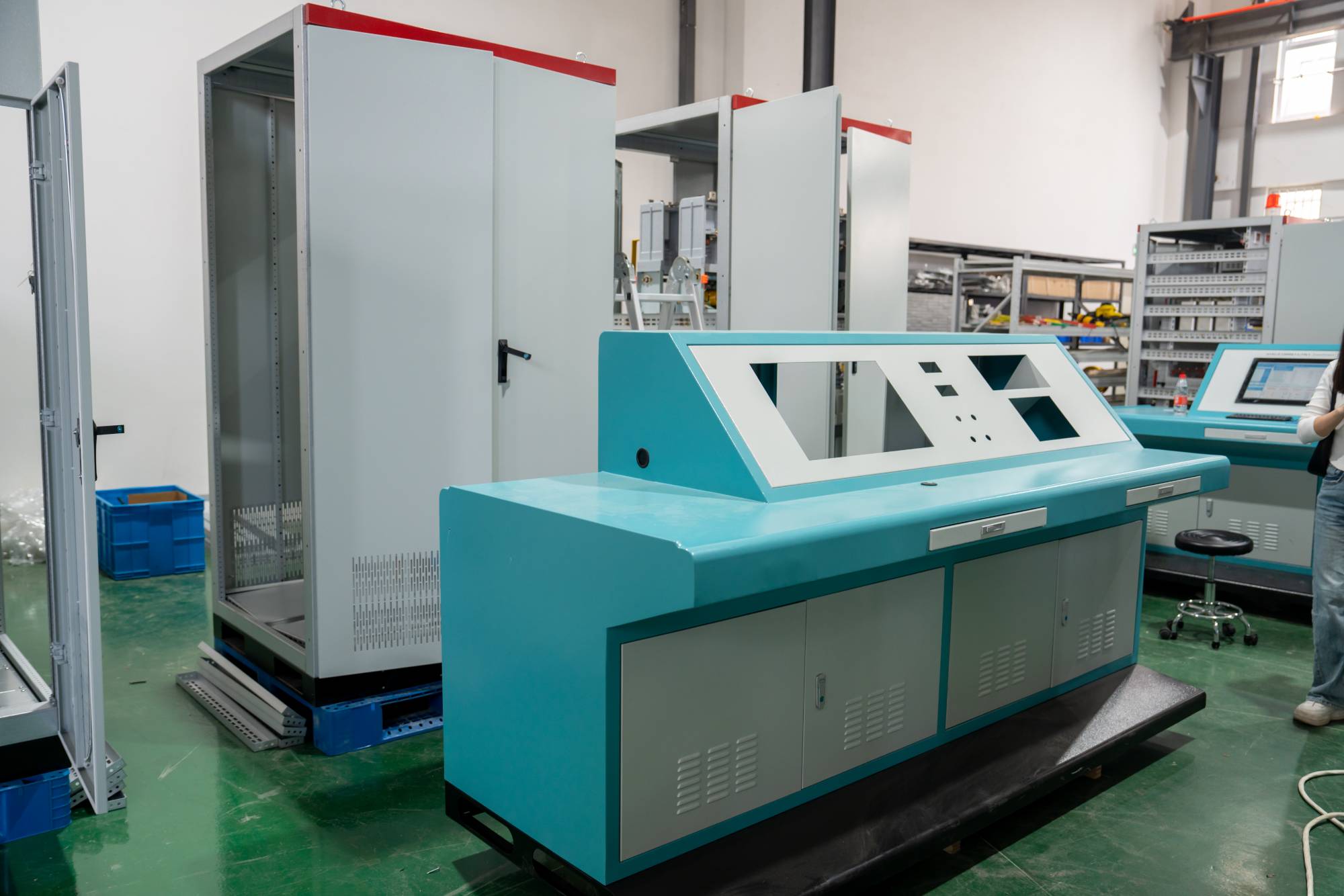
Transformer comprehensive test bench: the wisdom behind precise detection
2026-02-05Transformers, as an indispensable "heart" in the power system, their operational reliability directly affects the stability of the entire power grid. How can we ensure that these behemoths are foolproof before leaving the factory and during operation? The answer lies in the transformer comprehensive testing bench.What is a transformer comprehensive testing bench?Simply put, the transformer comprehensive testing bench is an automated equipment that integrates multiple detection functions, specifically designed for comprehensive and accurate performance and insulation status evaluation of power transformers. It is like a "versatile doctor" for transformers during physical examinations, capable of completing many key tests at once, greatly improving detection efficiency and accuracy.Factors affecting the accuracy of transformer testingThere are many factors that can "quietly" affect the accuracy of transformer testing results.Environmental factors such as temperature, humidity, and altitu
أكثر -
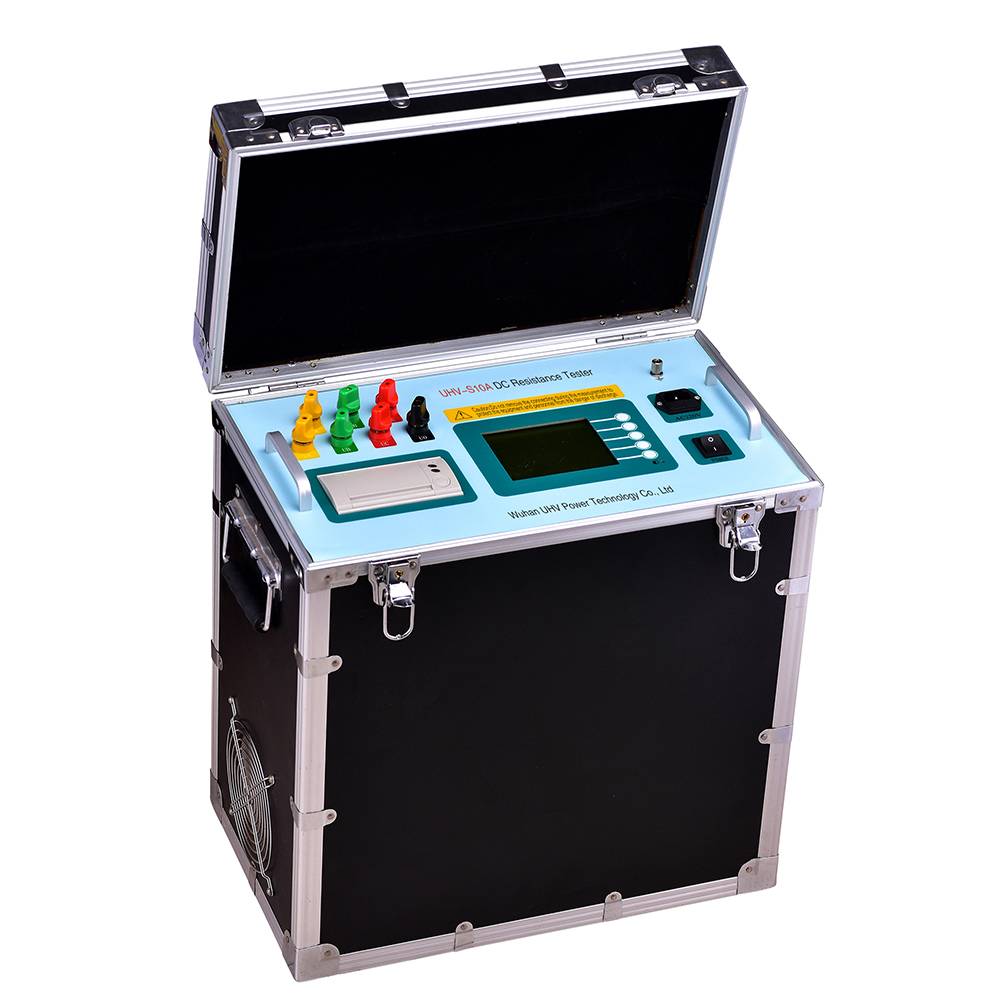
Don't rely on guessing anymore! Measuring the DC resistance of a transformer in this way doubles the efficiency!
2026-02-04As the "heart" of the power system, the operation status of transformers is directly related to the safety and stability of the power grid. And measuring its DC resistance is a key step in determining whether the transformer winding is intact, whether the contact is good, and how the tap changer performance is. In the past, we may have relied on some outdated methods with low efficiency and inevitable errors in the results. Today, let's talk about how to measure the DC resistance of transformers more efficiently and accurately, making this work easy and reliable.What is a transformer DC resistor?Simply put, the DC resistance of a transformer refers to the resistance value of the transformer winding in the DC state. The magnitude of this value directly reflects the cross-sectional area, material purity, and contact condition of the winding conductor at the connection point. Generally speaking, the smaller the DC resistance value, the smaller the energy loss of the transformer, and t
أكثر -
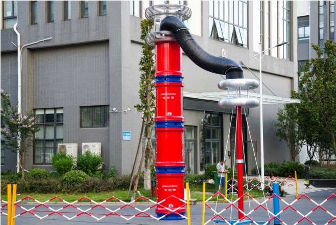
Series resonance: How does the "resonance" effect in electrical energy transmission affect efficiency?
2026-02-03Have you ever wondered why energy transmission becomes exceptionally efficient in some power systems, while encountering unexpected fluctuations at other times? Behind this, there is often a mystery called "series resonance". Today, let's unveil its mysterious veil together and see how it resonates, and what impact it has on our power transmission.What is series resonance?Simply put, series resonance is a circuit phenomenon where the inductance (L) and capacitance (C) components in a circuit experience a special "resonance" when they are connected at a specific frequency (resonance frequency). Imagine pushing a swing and giving it a push at the right time, and the swing will swing higher and higher. This is resonance. In a circuit, when the inductance (XL) of the circuit is equal to the capacitance (XC), it reaches a state of series resonance. At this point, the total impedance of the circuit becomes the smallest, exhibiting pure resistance, and the current will reach its maximum v
أكثر -
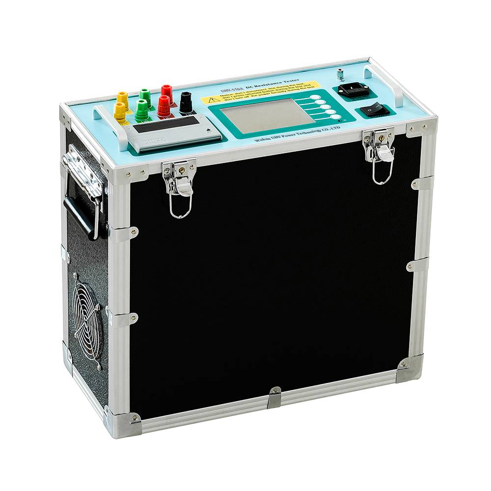
Transformer DC resistance meter: Why does it provide "invisible protection" for power safety?
2026-02-03In the power system, transformers play a crucial role, delivering surging energy like the heart. To ensure a smooth heartbeat of the transformer, a series of precise detection methods are indispensable. Today, let's talk about a "hero" who sounds a bit "hardcore" but silently guards power safety - the transformer DC resistance meter.What exactly is a transformer DC resistance meter?Simply put, it is a high-precision measuring instrument mainly used to measure the DC resistance of transformer windings. This value may seem insignificant, but it directly relates to the connection status, conductivity, and potential issues such as local overheating of the internal coils of the transformer.What factors will affect its measurement results?Temperature: The resistance value will change with temperature. In order to obtain reliable measurement results, temperature correction is usually required to convert it to standard temperature.Contact resistance: If the connection points inside the tra
أكثر -
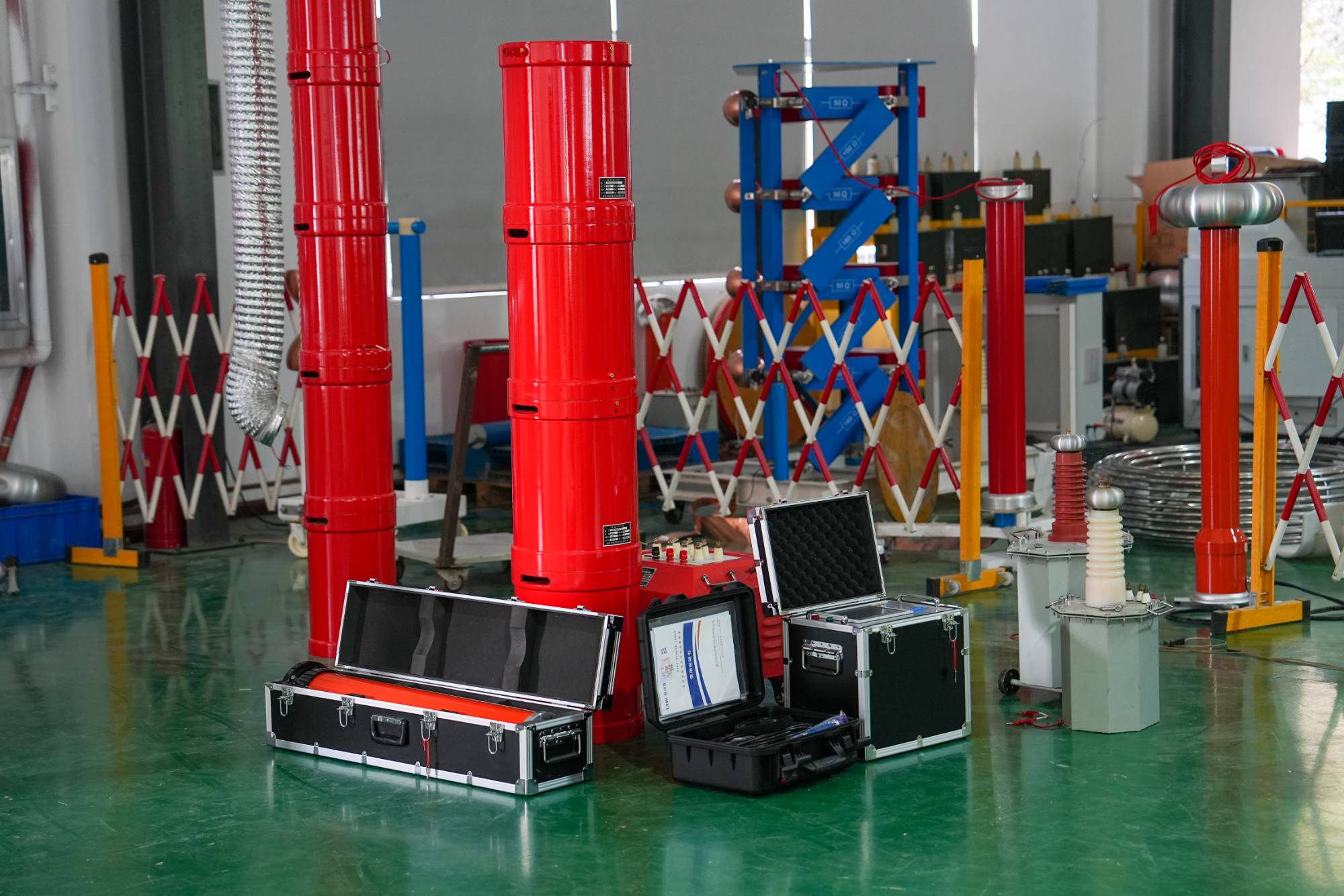
High voltage equipment 'inspector': Why is the AC/DC withstand voltage test device so important?
2026-02-02Ensuring the safe and stable operation of equipment is of utmost importance in the power system. Imagine if an important transformer or cable suddenly went on strike due to insulation issues, how much damage would it cause? At this point, a "health check-up officer" - an AC/DC withstand voltage testing device - is needed to conduct a comprehensive "health check-up" for high-voltage equipment.What is an AC/DC voltage withstand test device?Simply put, it is a device that can apply high voltage (including AC and DC) to detect the tolerance of insulation materials in electrical equipment when subjected to voltages above the rated working voltage. By applying different levels of voltage, we can determine whether there are defects in the insulation of the equipment, such as oil stains, moisture, material aging, etc., in order to detect potential risks in advance.What are the factors that affect the effectiveness of the withstand voltage test?Voltage level and waveform: Different devices requ
أكثر -
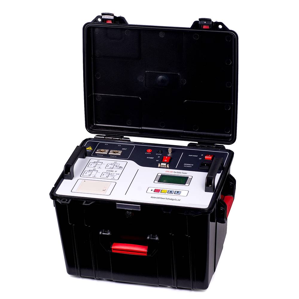
Dielectric constant dielectric loss tester: "health check-up officer" for power insulation
2026-02-02In the fields of power transmission and electronic equipment, the insulation performance of materials is crucial, and dielectric constant and dielectric loss are two key indicators to measure this performance. You may have heard of these terms, but what exactly are they? Why are they so important? Today, let's delve into the "health check-up officer" - the dielectric constant dielectric loss tester - that can accurately measure them.1、 The "ID card" of the measuring instrument: dielectric constant and dielectric lossDielectric constant: As the name suggests, it refers to the ability of a certain insulating material to store electric field energy under the action of an electric field. It's like a water absorbing sponge, the higher the dielectric constant, the stronger the material's ability to absorb electric field energy. In capacitors and other devices, high dielectric constant materials can help reduce volume and increase capacity.Dielectric loss: When alternating current
أكثر -
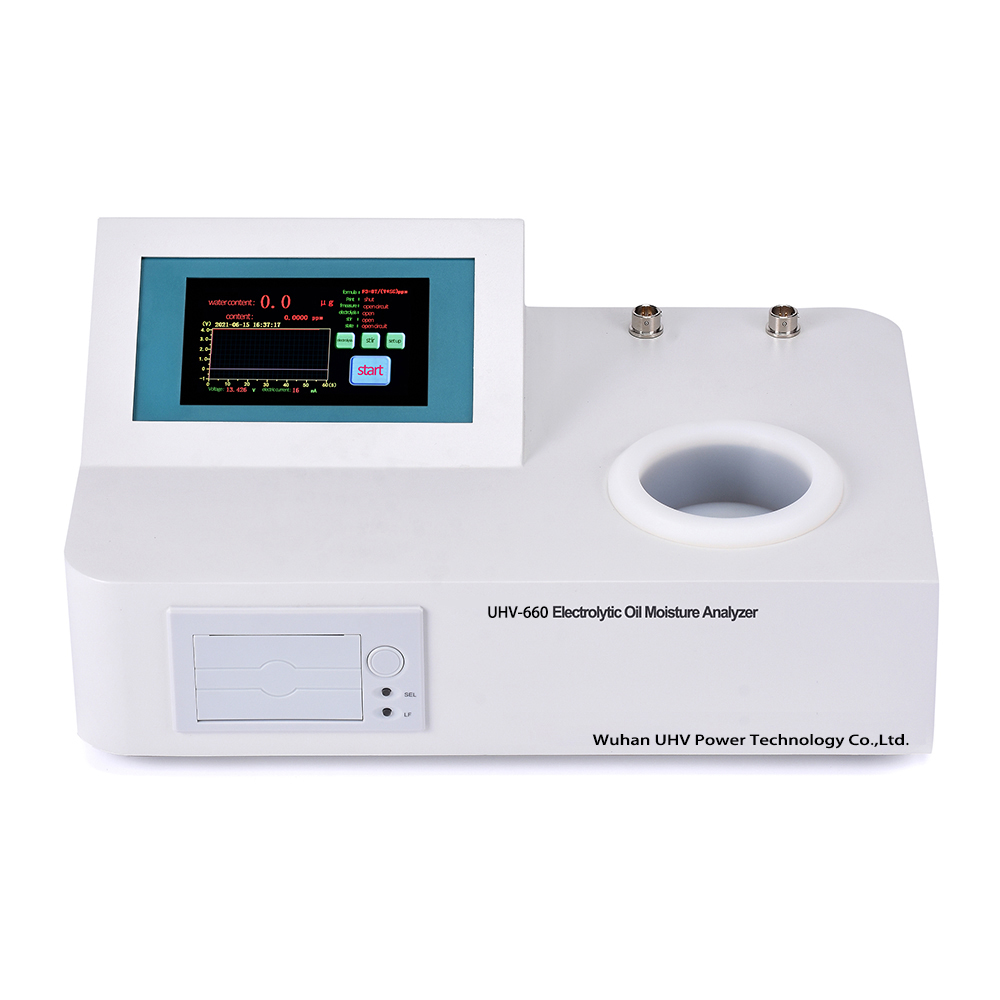
How to accurately measure trace amounts of moisture? The mystery of Karl Fischer water titrator
2026-02-02Accurate determination of trace moisture in samples is crucial in many industrial production and scientific research fields. Excessive or insufficient moisture content can have a serious impact on product quality, process stability, and even equipment lifespan. How can we efficiently and accurately capture these trace water molecules? The answer lies in the Karl Fischer water titrator.Karl Fischer titration instrument: a powerful tool for trace moisture determinationWhat exactly is it?Simply put, the Karl Fischer moisture titrator is an instrument specifically designed to determine the moisture content in a sample. It is based on the principle of Karl Fischer titration reaction, which calculates the moisture content in the sample by reacting chemical reagents with water and accurately measuring the consumed reagents. Compared to traditional drying methods, it has significant advantages such as fast speed, high accuracy, and wide applicability, especially in handling the determination o
أكثر -
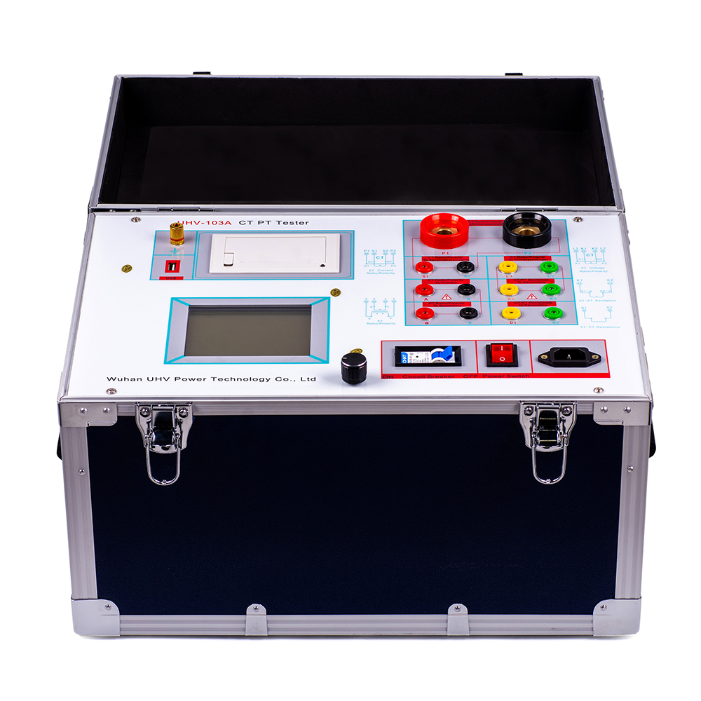
Unveiling the Voltage Current Characteristics Tester for Transformers: Key Technologies Behind Accurate Measurement
2026-01-29Transformers play a crucial role in the operation and maintenance of power systems, as they are responsible for converting high voltage and high current proportionally into low value signals that are easy to measure and protect. And the transformer volt ampere characteristic tester is our powerful assistant in revealing the "real face" of transformers. This sounds a bit professional equipment, what exactly is it? How does it work again? Today, let's talk about this topic together.What is the volt ampere characteristic of a transformer?We need to understand the concept of "volt ampere characteristics of transformers". Simply put, it measures the response of a transformer under different voltages and currents. An ideal transformer should be able to accurately transform signals according to its rated ratio. The transformer volt ampere characteristic tester uses advanced technology to detect the difference between the "true ratio" and the "ideal ratio", as well as the performance of th
أكثر -
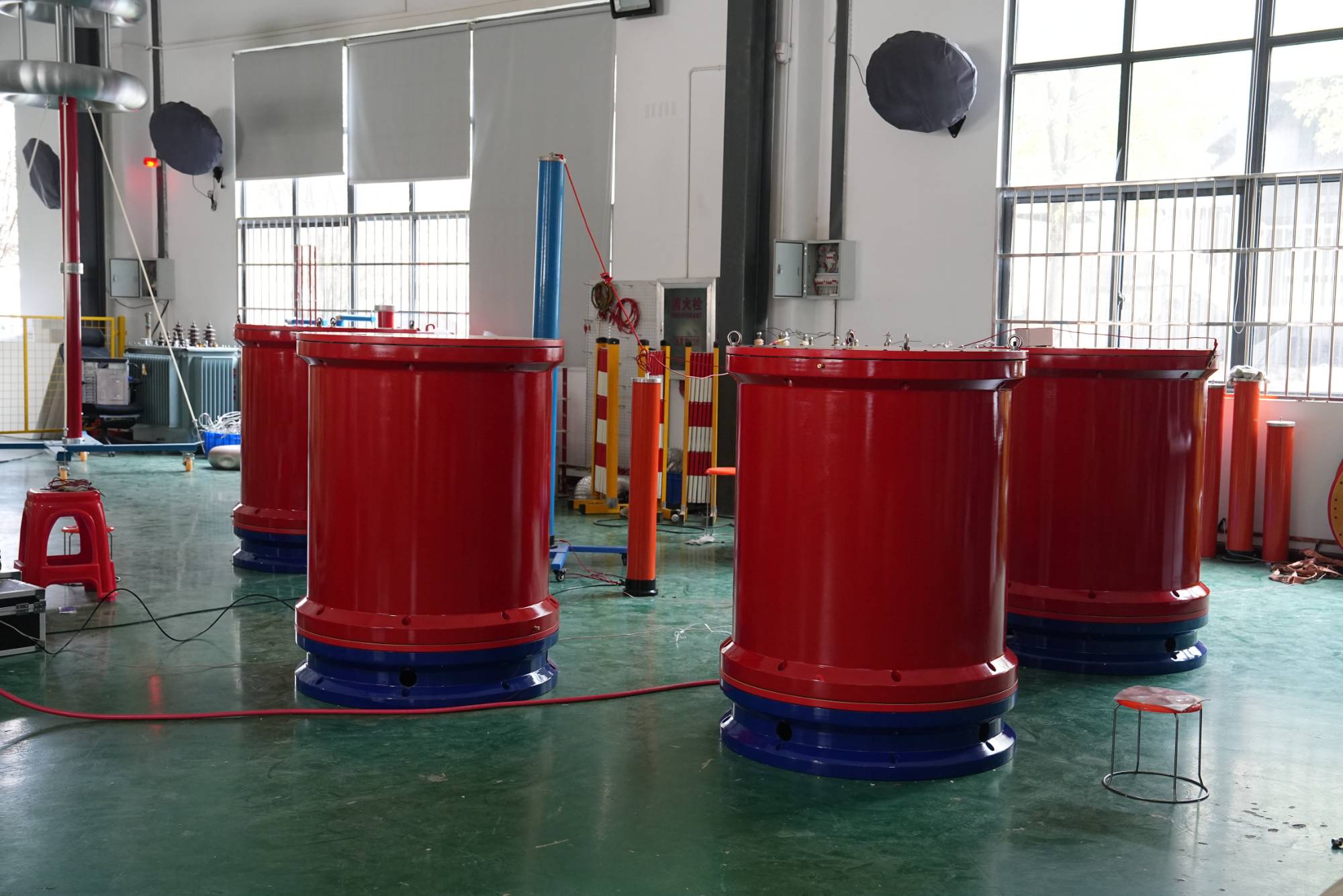
AC voltage withstand tester: the indispensable "guardian" of power safety?
2026-01-29Hey, colleagues in the power industry! Today, let's talk about a device that sounds a bit professional, but is actually closely related to our daily electrical safety - the AC voltage withstand tester. You may ask, this name sounds a bit tongue twisters, what exactly is it? Simply put, it is like a "health check-up doctor" for electrical equipment before it is put on duty, responsible for checking the "physical fitness" of the equipment when subjected to high voltage, ensuring that it can operate safely and reliably, and prevent "cylinder explosion".Why do we need a 'pressure test'?These days, power equipment is the "neural network" of cities, and once problems arise, the impact can be significant. The function of the AC voltage withstand tester is to simulate the high voltage environment that the equipment may encounter during actual operation, and see if it can "withstand" it. This is the "first line of defense" for key power equipment such as transformers, cables, and sw
أكثر -
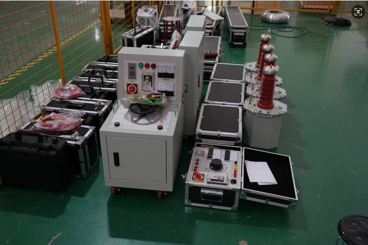
High Voltage 'Physical Examiner': Analyzing the Secrets of AC Voltage Test Devices
2026-01-29In the field of power equipment, ensuring its safe and stable operation is crucial. The AC voltage withstand test device is like a "health inspector" for power equipment, testing the insulation performance of the equipment by applying high voltage and promptly detecting potential risks. What exactly is it? What other factors can affect its' diagnosis' results? Don't worry, we will reveal them one by one for you.What is an AC voltage withstand test device?Simply put, an AC voltage withstand test device is a high-voltage equipment used to test the insulation strength of electrical equipment. It can simulate the overvoltage situations that equipment may encounter during operation, and determine whether its insulation level is qualified by observing whether the equipment has breakdown or insulation damage. This plays an irreplaceable role in ensuring the safety of the power grid and preventing equipment failures from causing large-scale power outages.Factors affecting the effec
أكثر -
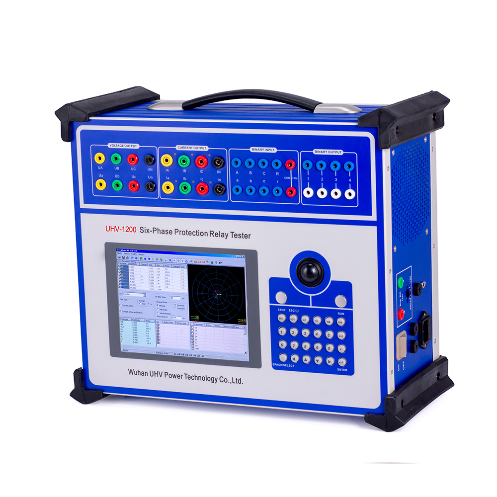
Mastering the "Six Phase Microcomputer Relay Protection Tester": What You Need to Know from Beginner to Proficient!
2026-01-29Behind the safe operation of the power system, there is a group of silent "guardians" who are relay protection devices. To ensure that these "guardians" are always in the best condition, we cannot do without our protagonist today - the six phase microcomputer relay protection tester. Does it sound a bit 'high-end'? Don't worry, I'll take you through it easily today!Unveiling: What is a six phase microcomputer relay protection tester?Simply put, it is a set of "medical examination doctors" used to detect and debug the "invisible guards" in the power system - relay protection devices. Why is it called 'Six Phases'? Because modern power systems are often three-phase, and a complete set of protection functions may require simulating multiple signals from different phases, the "six phase" can more comprehensively and accurately simulate various operating and fault conditions, and conduct a comprehensive "physical examination" of the protection device. Microcomputer "
أكثر -
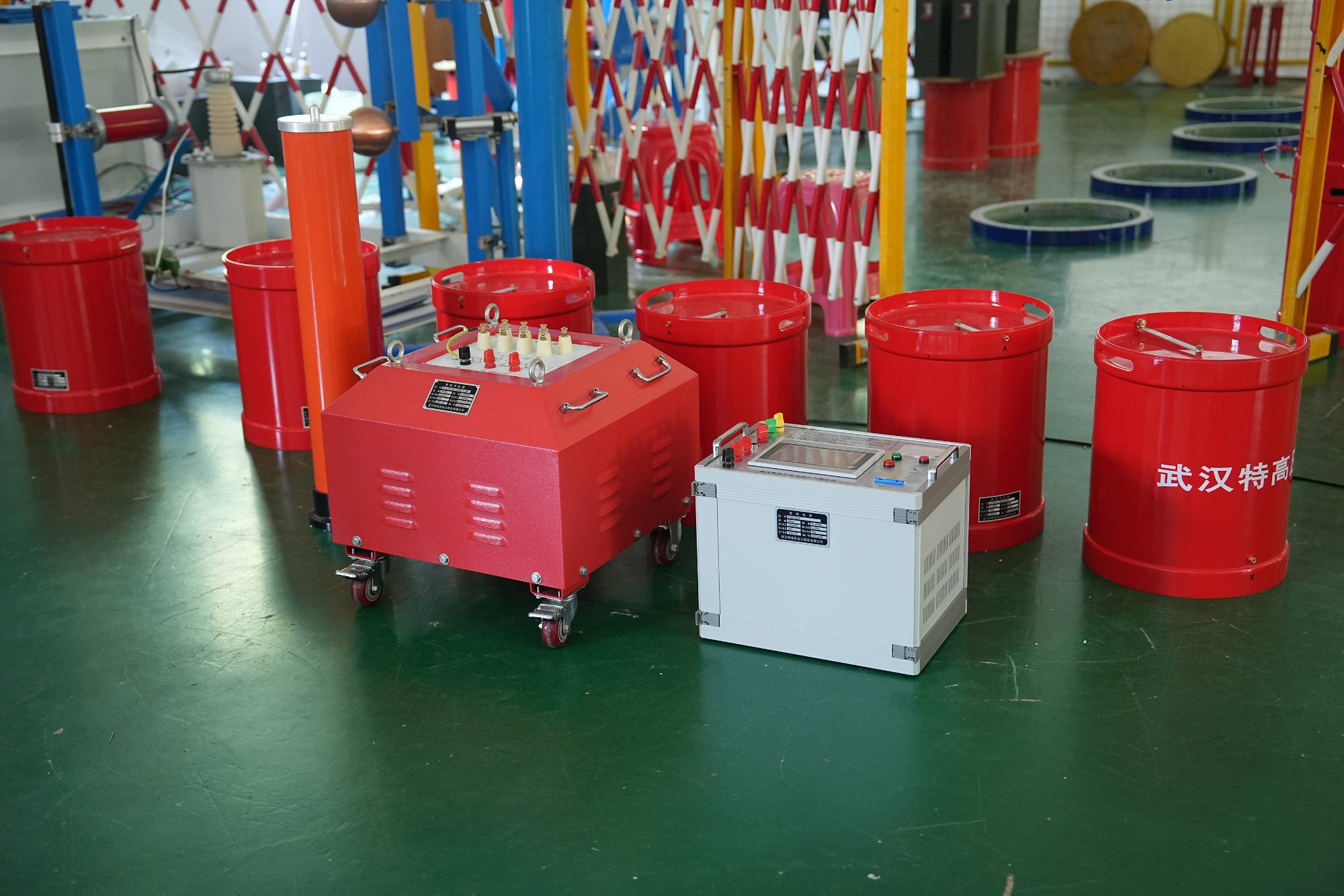
Series resonance test equipment: the "guardian" of safe operation of power systems
2026-01-28The power system, this massive 'neural network', is indispensable in our daily lives. To ensure the stable and secure operation of this' neural network ', a series of rigorous testing and maintenance work are required. Today, let's talk about a very important "tool" in the field of power equipment testing - series resonance testing equipment.What is a series resonance test equipment?Simply put, series resonance testing equipment is a specialized instrument used for conducting partial discharge, dielectric loss, and other tests on high-voltage power equipment. It adjusts the parameters of inductance and capacitance to make the circuit in a resonant state, thereby generating a high test voltage on the tested equipment. It's like tuning an instrument, when the frequency is the same, it can produce the strongest resonance, and the series resonance test equipment uses electromagnetic "resonance" to "auscultate" the "health status" of high-voltage equipment.Influencin
أكثر -
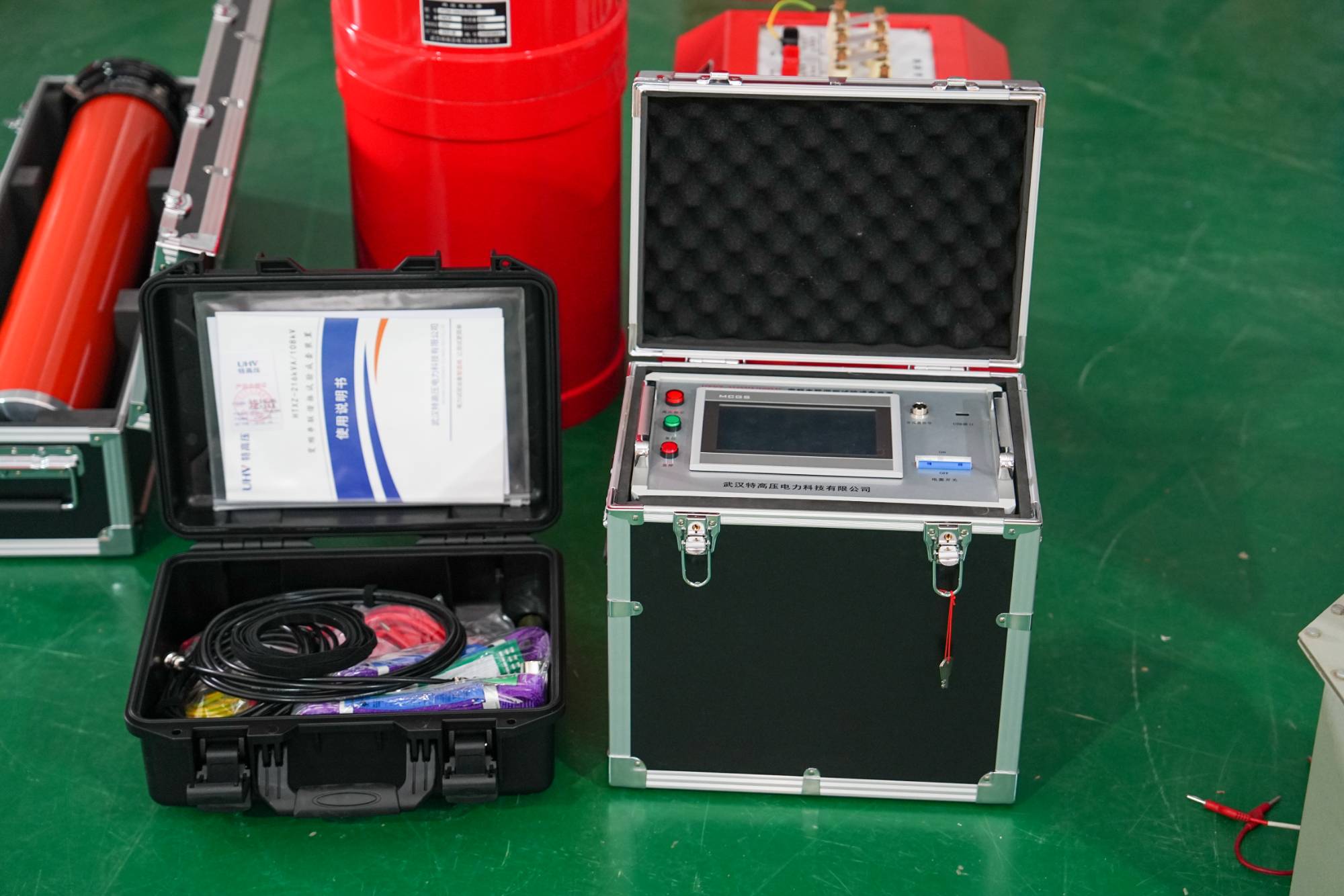
Say goodbye to ambiguity! The series resonance test device takes you through the "clear" moments of high-voltage electrical testing
2026-01-28In the world of high-voltage electrical equipment, a "physical examination" before each operation is crucial. Among various detection methods, the series resonance test device plays an indispensable role. Have you ever been curious about this device that sounds a bit "hardcore"? What exactly is it? Why is it so important in high-voltage testing? Today, let's unveil its mysterious veil together and see how it helps us ensure the stable operation of the power system.What is a series resonance test device?Simply put, a series resonance test device is an AC test power supply that can generate high voltage and high current. Its core lies in utilizing inductance L and capacitance C to form a "resonance" phenomenon at a specific frequency, thereby easily obtaining the required test voltage without the need for bulky or large transformers. This device is particularly suitable for voltage withstand testing of large high-voltage electrical equipment such as cables, transformers, GIS (gas ins
أكثر -
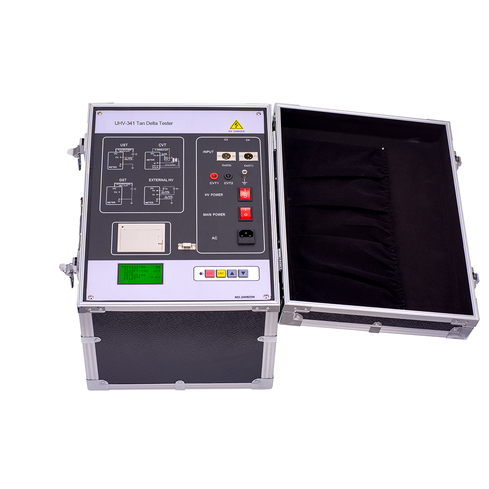
Dielectric constant and dielectric loss: why are they the "health check" for insulating materials?
2026-01-26Are you curious why some materials can safely isolate current while others leak heavily? Behind this, the two key indicators of dielectric constant and dielectric loss play important roles. Today, let's talk about what they are and how they affect the safe operation of our power equipment.What are dielectric constant and dielectric loss?Simply put, the dielectric constant (also known as relative permittivity) reflects a material's ability to store electric field energy under the action of an electric field. The higher the value, the stronger its ability to store electric field energy. Imagine, it's like the material's ability to absorb energy.And dielectric loss is the phenomenon of energy loss inside insulating materials under the action of an electric field, and this lost energy is usually converted into heat. The lower the value, the less "energy waste" the material has, the poorer its thermal conductivity, the less likely it is to generate heat, and the better its i
أكثر -
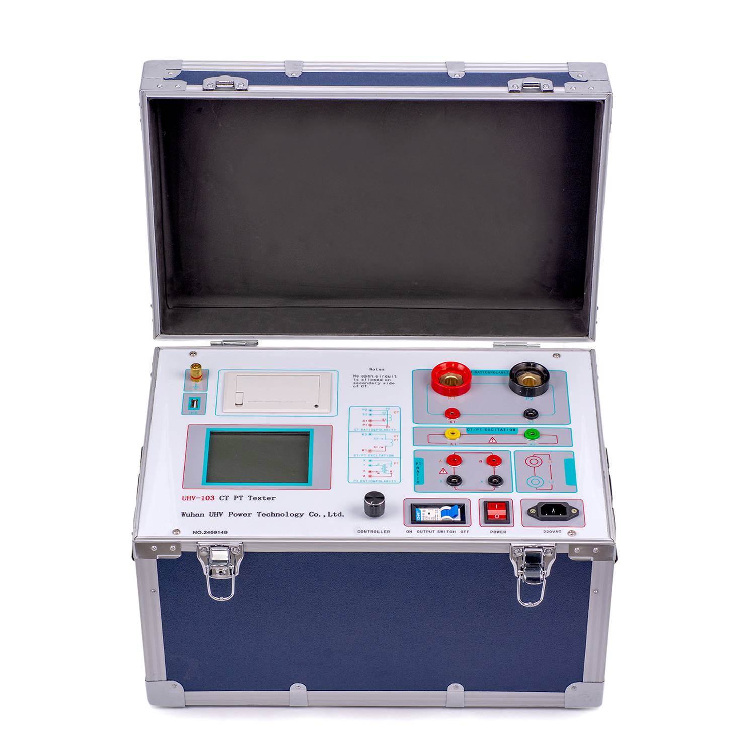
Say goodbye to estimation! Exploring how the "volt ampere characteristic tester" accurately depicts the "personality" of the equipment
2026-01-26In the world of power equipment, each component has its own unique "personality", which is largely reflected in its "volt ampere characteristics". Imagine if we could have a tool that can clearly depict the "volt ampere characteristics" of a device like a physical examination? The answer is yes, this is the "volt ampere characteristic tester" we are going to talk about today.What is volt ampere characteristic?Simply put, the "volt ampere characteristic" is a graph that describes the relationship between the operating states of an electrical component (such as a transformer, transformer, motor, etc.) under different voltage (V) and current (A) conditions. It is like the "fingerprint" of a device, which can accurately reflect the internal structure, material characteristics, and potential defects of the device.What are the factors that affect the volt ampere characteristics?The properties of the material itself, such as the resistivity of the conductor and the dielectric constant of the
أكثر -
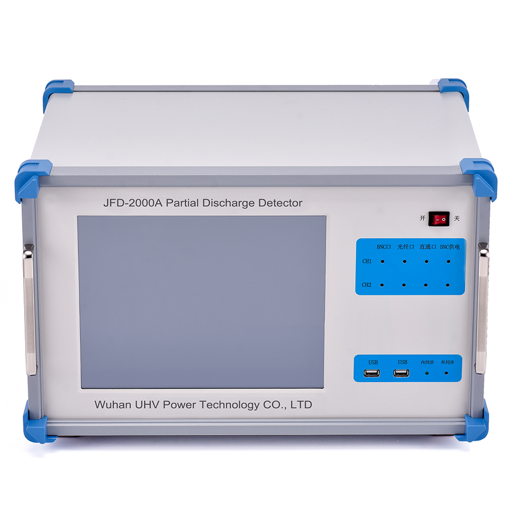
Digital partial discharge detector: the secret of the "health check-up specialist" for power equipment
2026-01-26The power system is like the circulatory system of the human body, and the health of power equipment directly affects the stable operation of the entire system. Among many "health killers", partial discharge is one of the "culprits" that cause insulation aging, equipment damage, and even major accidents. How can we promptly detect and 'diagnose' this latent danger? The answer is - digital partial discharge detector!What is a digital partial discharge detector?Simply put, this is a high-tech "stethoscope" and "microscope" specifically designed to capture the weak but highly destructive "partial discharge" phenomena inside electrical equipment. It converts the electrical pulse signals generated inside the device into digital information through highly sensitive sensors, and then undergoes complex analysis and processing, allowing us to intuitively understand key information such as discharge intensity, frequency, and type. This is like performing a precise 'magnetic resonance
أكثر -
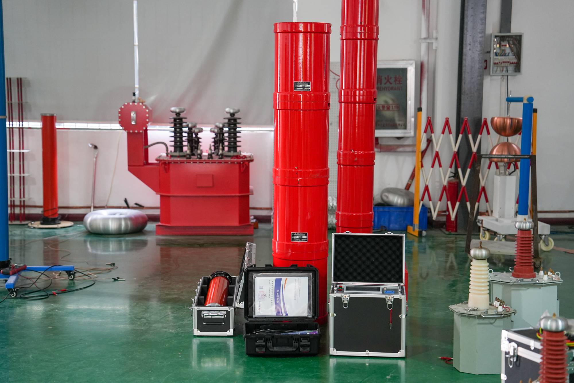
Playing with High Voltage Testing: What is Series Resonant Voltage Endurance Equipment?
2026-01-26In the field of high-voltage testing of power equipment, "series resonant withstand voltage equipment" is an unavoidable topic. It sounds a bit technical, but don't worry, today we will use the most down-to-earth way to explain it clearly.What is series resonance? The 'secret weapon' behind thisSimply put, series resonance is a circuit phenomenon that occurs when the inductance and capacitance in a circuit exchange energy at a specific frequency (i.e. resonance frequency). In power equipment testing, we use this principle to construct a system that can generate a huge test voltage, which is commonly referred to as a "series resonant withstand voltage device".Why do we need it?Imagine those transformers, cables, and switchgear that often operate at hundreds of thousands of volts. They need to undergo a "physical examination" before use to ensure stable operation in high voltage environments and prevent them from being easily triggered. The traditional voltage withstand test
أكثر -
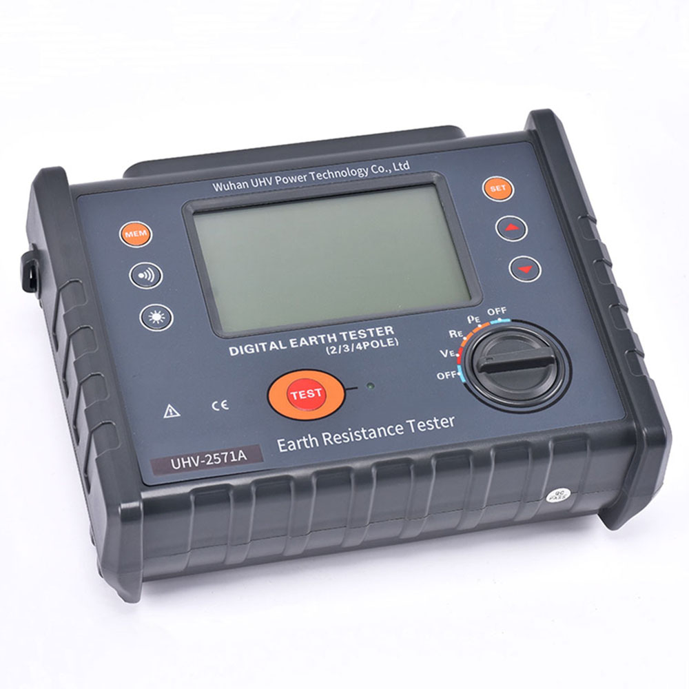
Why does your grounding system require a ground resistance meter tester? Don't let security risks come quietly!
2026-01-23Have you ever thought about the security system hidden behind the electrical equipment we use in our daily lives? Among them, "grounding" is like installing a "safety valve" on the power system, and the "grounding resistance meter tester" is a powerful assistant to check whether the "safety valve" is working properly. Today, let's talk about this seemingly insignificant but crucial device.Grounding resistance meter tester: the "eye" guarding safetyWhat is grounding resistance?Simply put, grounding resistance is the total resistance of current flowing from the earth through the grounding device, then to the grounding grid, and finally back to the metal casing or neutral point of the equipment. The smaller the resistance value, the better the grounding. Once leakage or short circuit occurs, the current can be quickly introduced into the ground, greatly reducing the risk of electric shock.Why does the grounding resistance need to be tested?The effectiveness of grounding systems is not
أكثر -
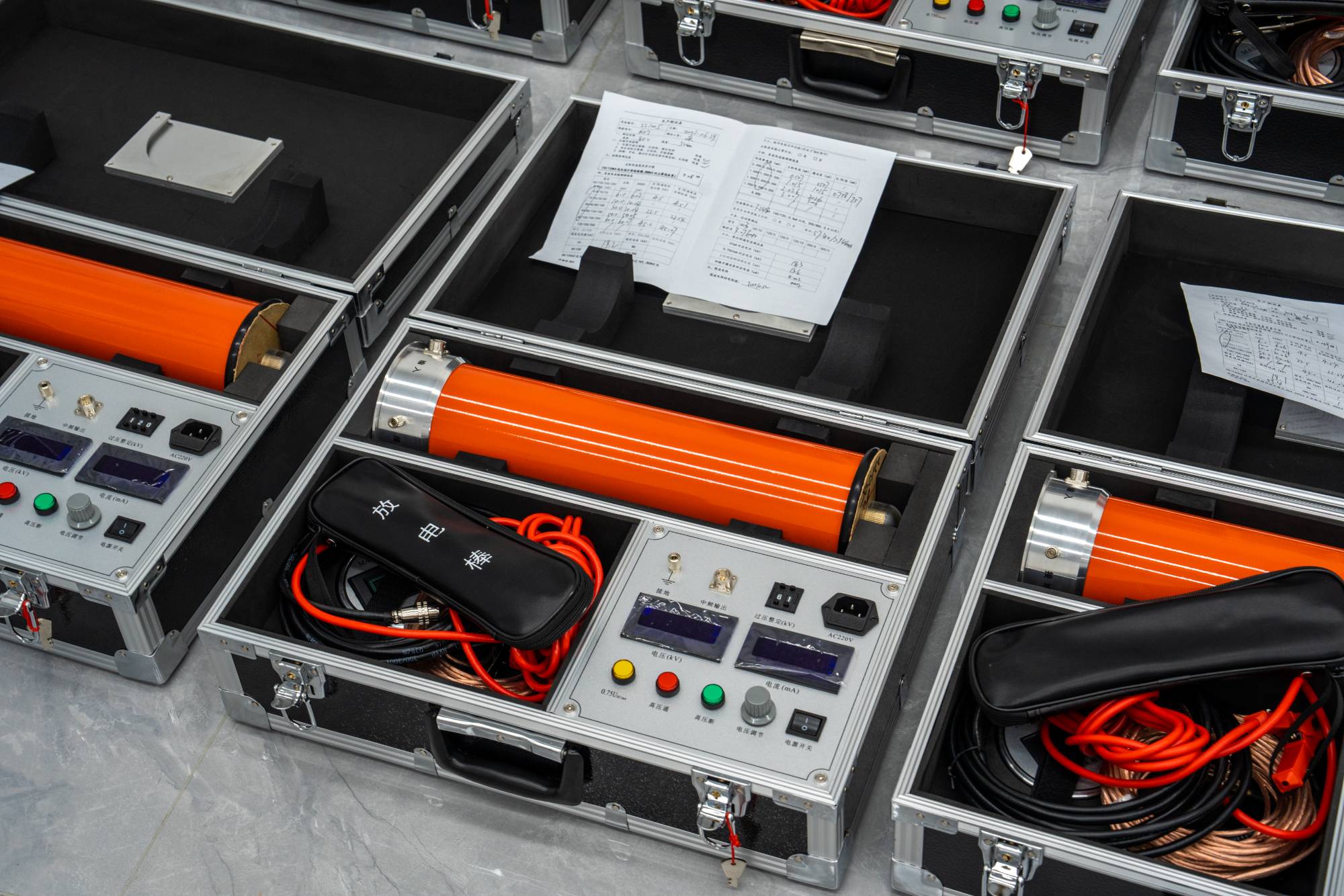
Unveiling the Medium Frequency DC High Voltage Generator: The 'Behind the Scenes Hero' of Power System Testing!
2026-01-23In our power system, the stability of various equipment operations is crucial. Do you want to know if they are "physically amazing"? Then the 'mid frequency DC high voltage generator', the 'behind the scenes hero', is indispensable! It sounds a bit professional, but when broken down, it's actually not that mysterious.What is a 'medium frequency DC high voltage generator'?Simply put, it is like a precision instrument used for "physical examination" of electrical equipment. By generating a stable and controllable 'high-voltage direct current', the insulation performance of electrical equipment (such as transformers, cables, insulators, etc.) can be tested. Think about it, if there are "minor problems" inside the device, they can be easily exposed under strong high pressure, so that we can detect them in advance and avoid big trouble caused by "running with problems".What are the factors that affect the effectiveness of physical examinations?To make thi
أكثر


