
Product List
اتصل بنا
البريد الإلكتروني: qiao@hvtest.cc
الجوال: +8615871365102
ما هو التطبيق: +8615871365102
-

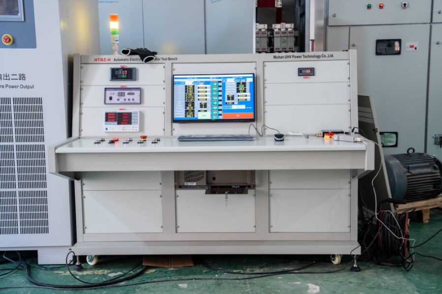
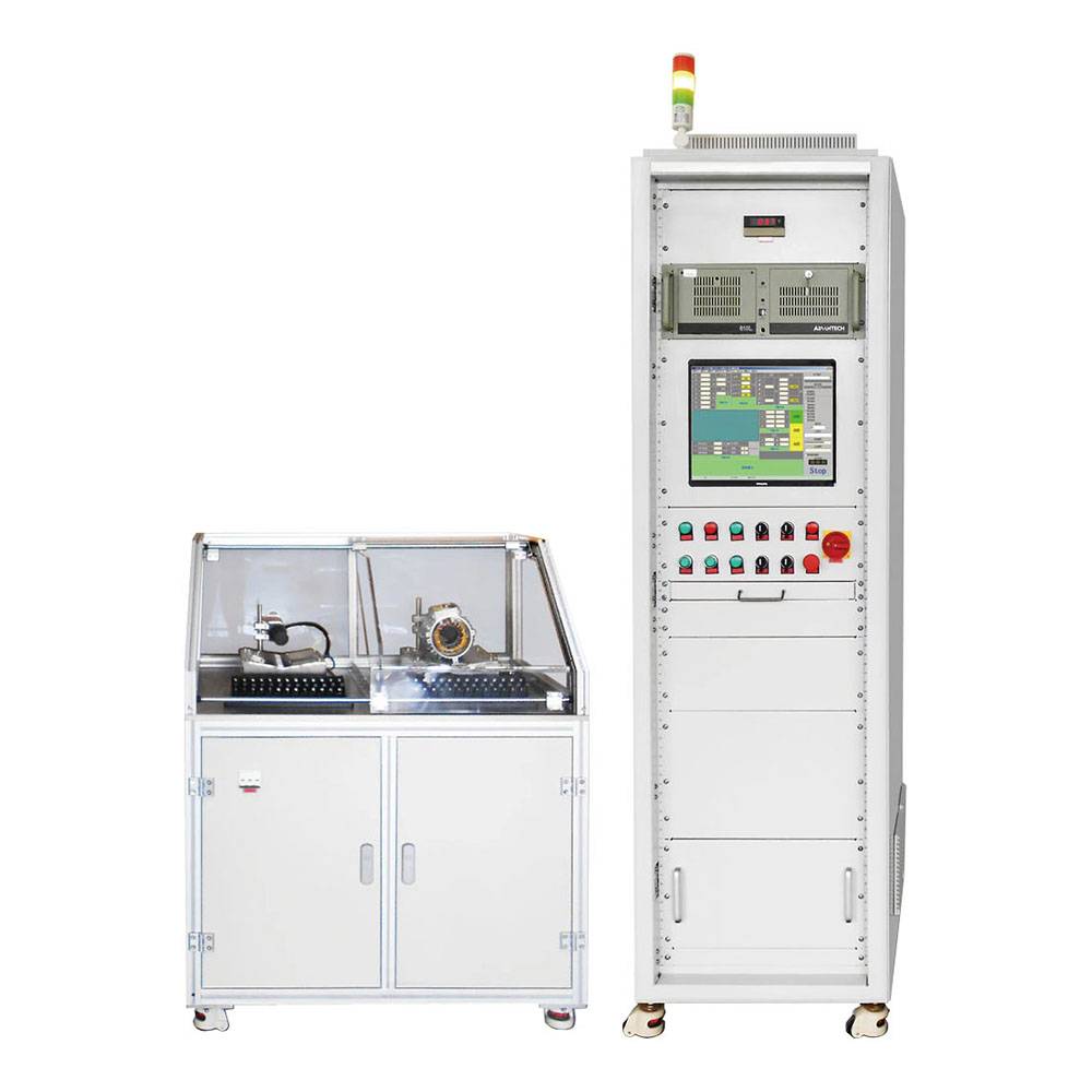
Function of motor type test bench system test software
2026-07-141. Torque, speed, current, voltage, power, power factor, power frequency meter and other interfaces are automatically collected by 485/232. Temperature and resistance are input into the computer through a keyboard, and the computer processes, displays, reports, fits curves, prints, etc.2. The asynchronous motor microcomputer testing system software has completed no-load test, blocking test, load test, temperature rise test, etc., and can automatically complete data reports and curves.3. The software can process data through testing:(1) Can conduct A and E method experiments(2) The system is capable of conducting no-load tests, leakage tests, temperature rise tests, and load tests on single-phase and three-phase asynchronous motors.(3) The system can display real-time motor three-phase voltage, three-phase current, input power, frequency, power factor, torque, speed, output power, and efficiency.(4) The system can record real-time data during the temperature rise test process. It is div
أكثر -
Fault diagnosis analysis of AC motor type test bench
2026-07-14The AC motor type test bench is a driving force for social development, and the development of motor technology is moving towards efficiency, reliability, and low cost!There are various types of motors, roughly including DC motors and AC motors. There are many types of electric motors, and their usage scenarios are also different.Regardless of the type of motor, various fault phenomena will occur during use, which can be divided into mechanical and electrical parts. The following provides a detailed analysis of the causes and symptoms of the malfunction.53% of faults come from mechanical parts, such as bearing failures, imbalances, looseness, etc. 47% comes from the electrical part, of which 10% comes from the rotor (unbalanced air gaps, segment bars, etc. caused by casting defects, and 37% comes from the stator coils)Reasons for failure: 24% overload, 17% humidity, 20% lack of lubrication, 1% chemical pollution, 5% dust particles, 10% single-phase operation, 12% bearing failure, 5% in
أكثر -
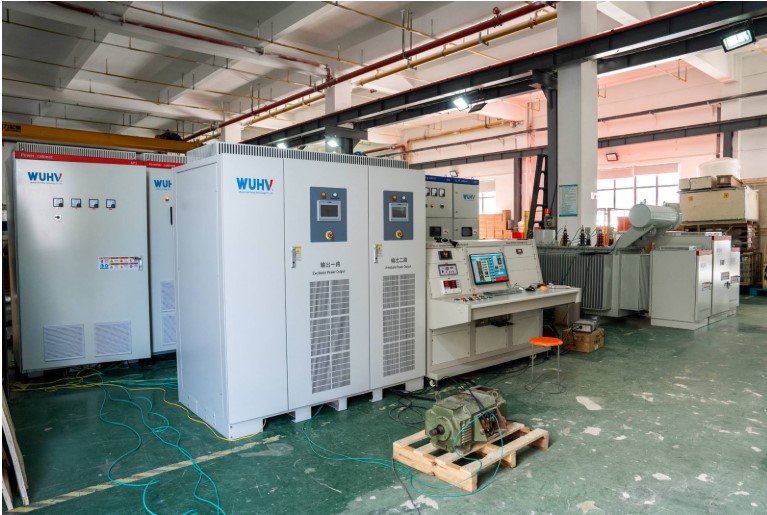
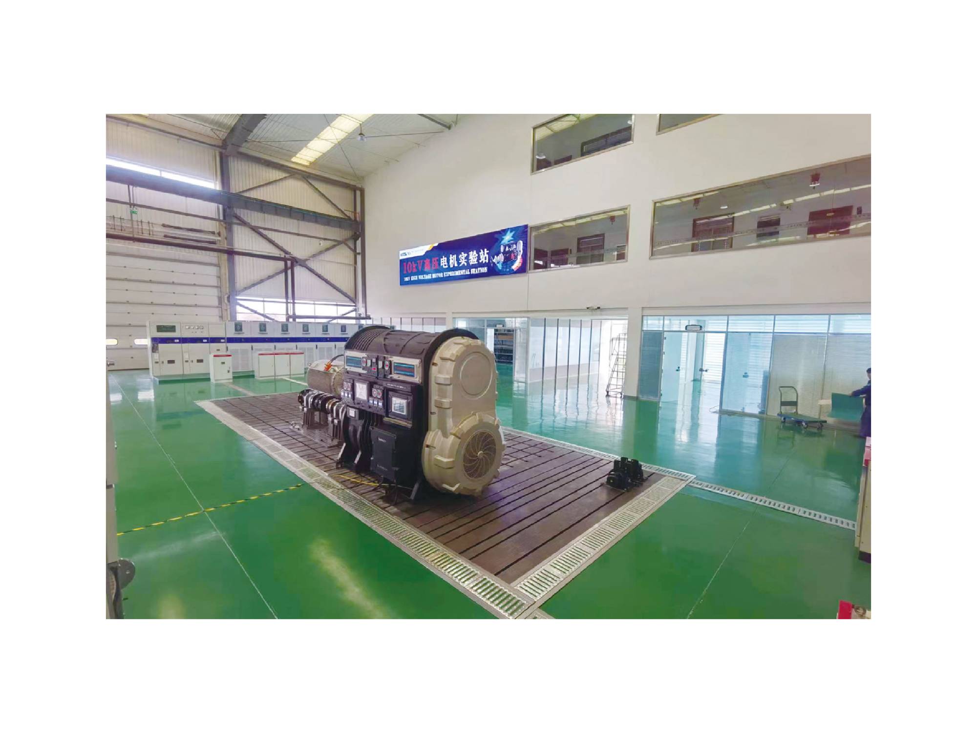
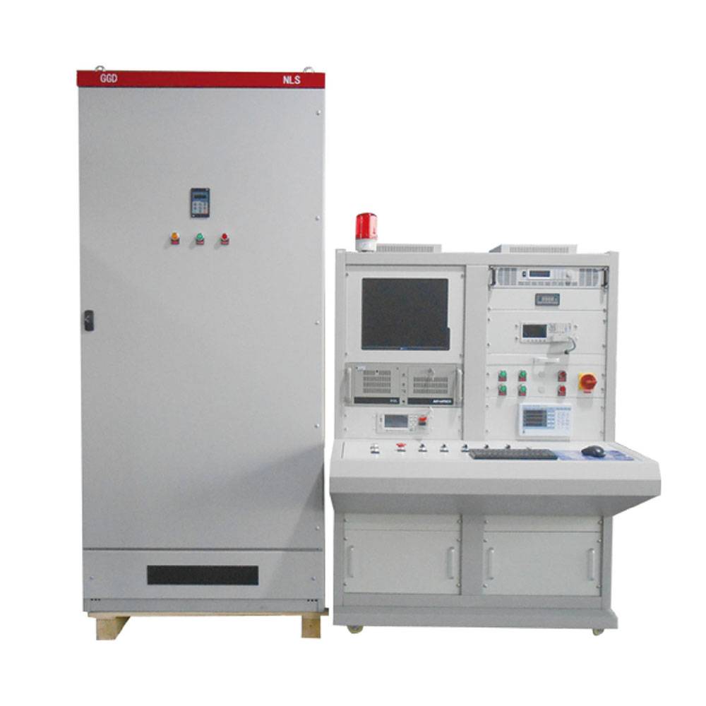
Composition of high-voltage motor test bench
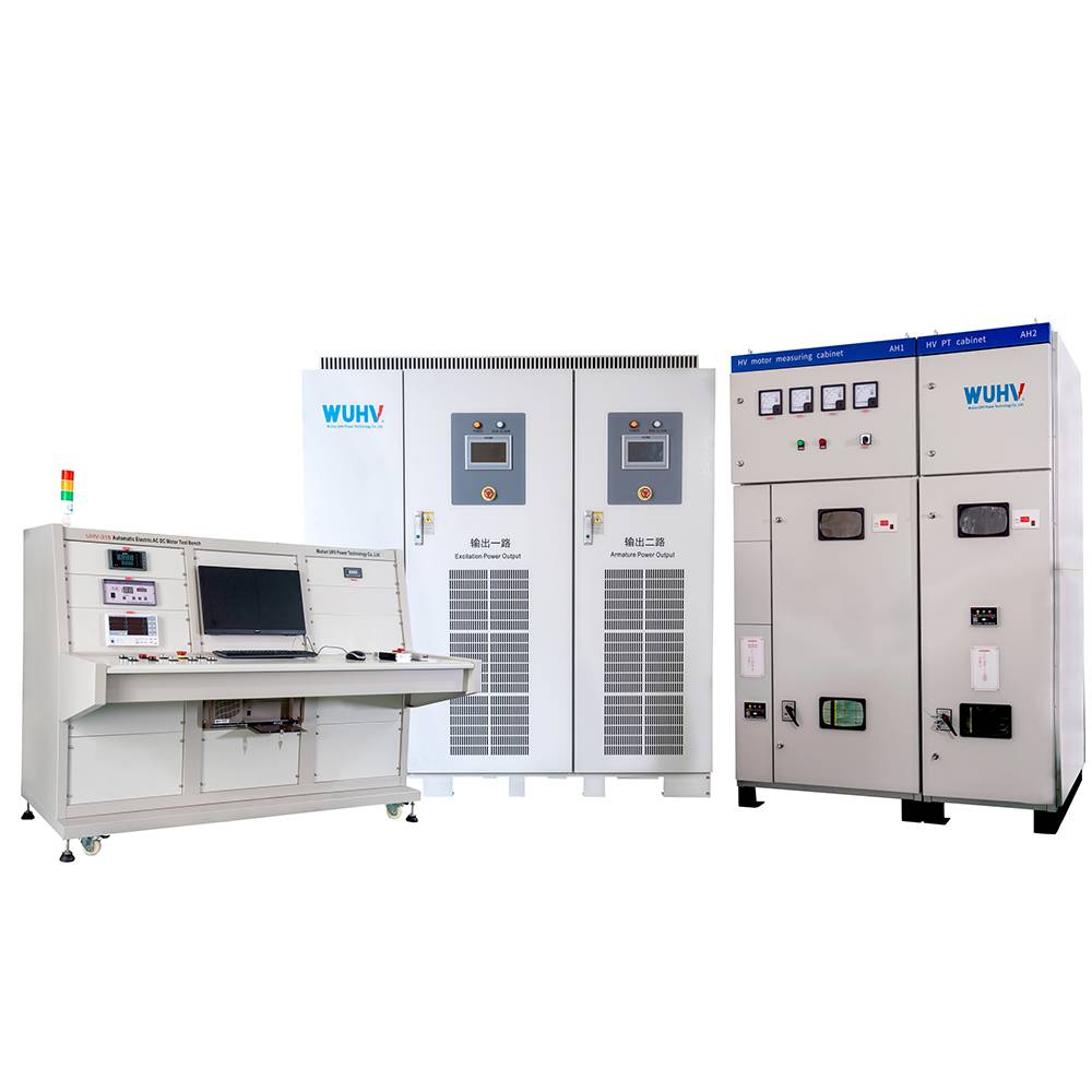
2026-07-13With the implementation of the national motor energy efficiency improvement plan, in response to the call for "energy conservation and emission reduction", the demand for motor test benches from various motor manufacturers and testing units is increasing. High voltage motor test benches are mainly used for motor type testing, factory testing, and energy efficiency evaluation. The system mainly includes three parts: test power supply, testing system, and operating platform. Among them, testing the waveform quality of the power supply and the accuracy of the testing system are the key factors affecting the scientific and accurate data of the test results.The fully automatic motor comprehensive testing platform adopts advanced virtual instrument technology, combining the powerful computing power of computers with the hardware measurement and control capabilities of instrument equipment. It is reliable and reliable to use, and the main items are displayed in color with Chinese operation pr
أكثر -
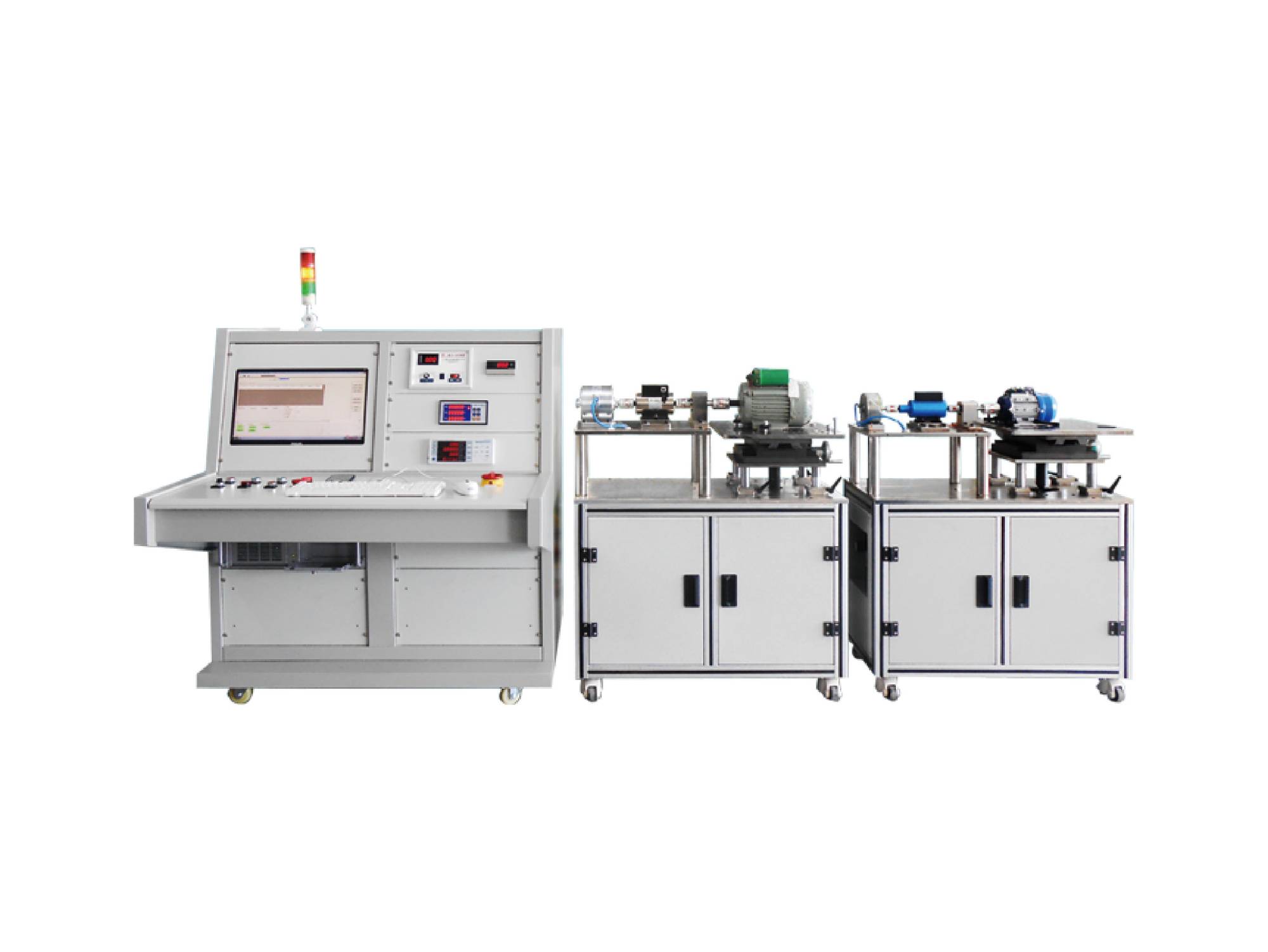
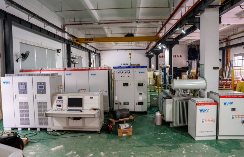
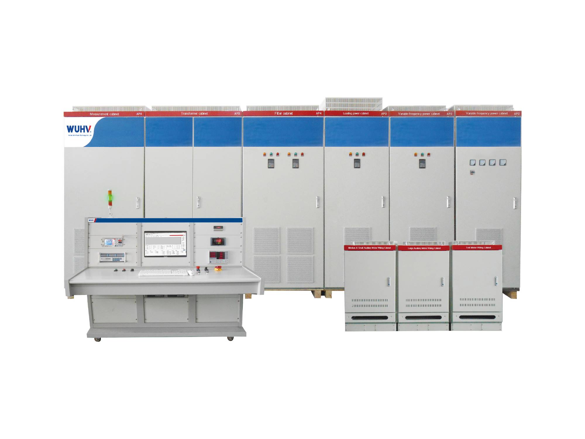
AC motor test bench testing system
2026-07-13The AC motor test bench consists of a test power supply, an electrical parameter testing system, a testing and control system, and motor detection and control report software. The experimental bench uses two test power sources to drive and drag two motors, one for motor operation and the other for generator operation. The test power source uses a static variable frequency power source, and the two test power sources share a rectifier unit. The electrical energy generated by the generator is reverse rectified by the test power source into DC power and supplied to the inverter unit of the motor operation. The power grid only needs to supplement the losses of the two motors to obtain about 70%.The electrical parameter testing system adopts a variable frequency power testing system composed of a variable frequency power sensor and a variable frequency power analyzer. Thus, it can meet the testing requirements of low-frequency stall and overspeed of power frequency motors, as well as the te
أكثر -

Physical principles of three-phase asynchronous motor test bench
2026-07-10Asynchronous motor test bench and synchronous motor belong to AC motors, and according to the number of phases, there are single-phase asynchronous motors, three-phase asynchronous motors, single-phase synchronous motors, and three-phase synchronous motors. We will take the three-phase asynchronous motor test bench and three-phase synchronous motor as examples to explain the working principle of AC motors.When three-phase asynchronous motors and three-phase synchronous motors are in operation, their three-phase stator windings are connected to a three-phase AC power supply, which provides three-phase AC current and generates a rotating magnetic field inside the motor. This magnetic field connects the stator winding and rotor winding, realizing the transfer and conversion of energy from the stator to the rotor. Therefore, the conversion of the rotating magnetic field and force of an AC motor is the key to its operation.First, let's take a look at some basic knowledge about magnetic
أكثر -

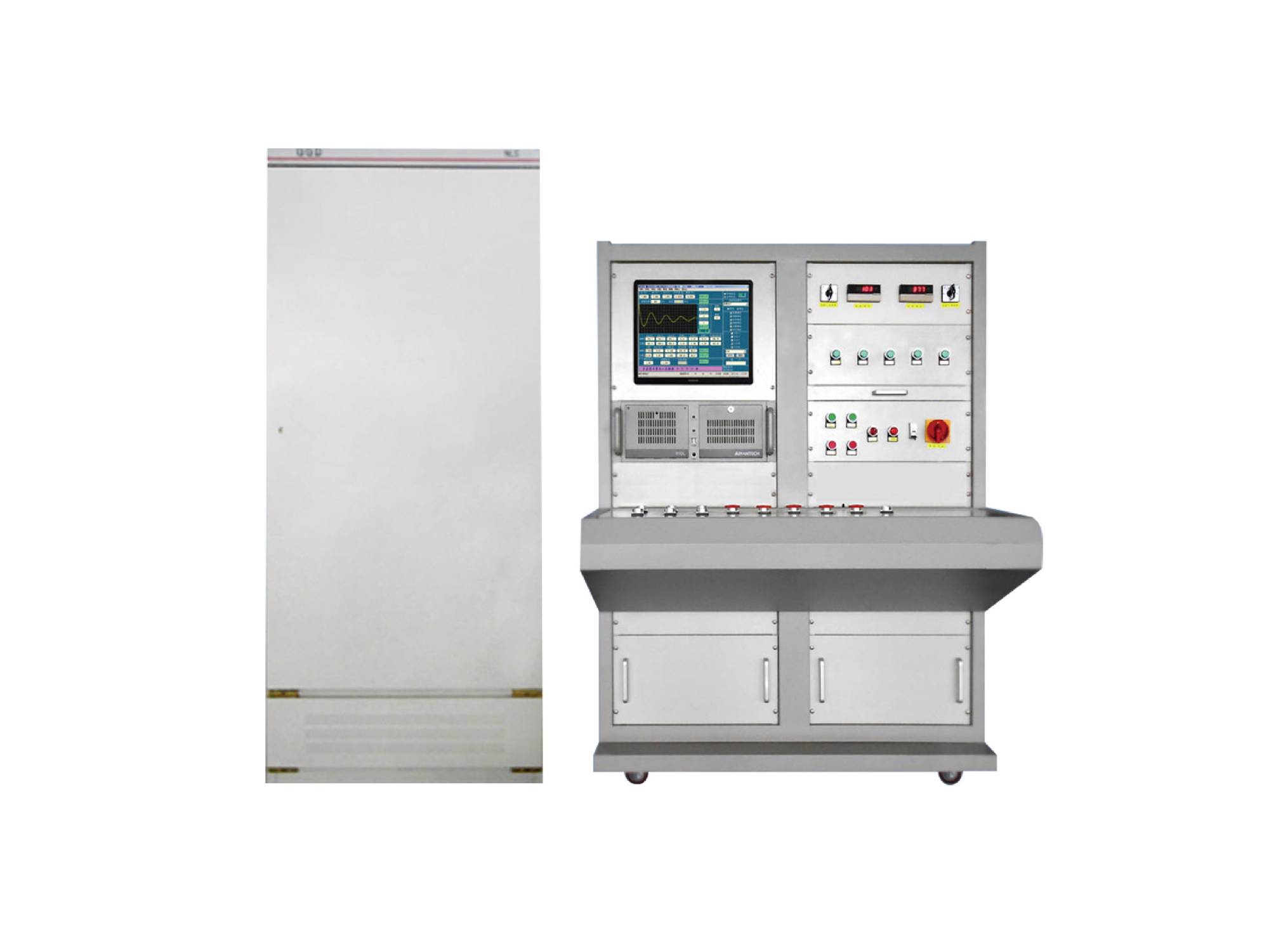
Introduction to the Operation of Motor Type Test Bench
2026-07-10Motor type testing is a comprehensive testing project that evaluates the consistency between the product and design, as well as its application effectiveness. Better motor manufacturers, on the other hand, will conduct necessary simulation experiments based on different working environments, that is, to conduct more tests that closely resemble the actual working environment to the maximum extent possible, in order to avoid product quality problems caused by substandard performance.1. Under what conditions should the motor type test bench be conducted?Testing is a comprehensive prediction of the performance, performance, and performance of a product based on its technical specifications and the applicability of production processes. Type testing is usually conducted under the following conditions:After the testing of the new product is completed, the performance of the sample is tested to determine the finalization and improvement of the product, which serves as auxiliary information.Du
أكثر -
Common faults of asynchronous motor test bench
2026-07-091. Electrochemical destructionIn the gas production workshop of a certain factory, two motors have malfunctioned. One of the stator windings has three insulation ruptures, and an area has "creepage" with burn marks, cracks, and conductive channels. The faulty parts are all near the motor's air inlet and have a tendency to shift towards the dead center. We began to believe that the layout, operating environment, and control methods of the electric motor system were unreasonable, and the harsh operating environment led to electrochemical breakdown.The main cause of insulation damage in asynchronous motor test benches is the electrochemical damage caused by harsh operating environments. The acidic and alkaline corrosive gases present in the environment can corrode the outer layer of insulation materials. In high environments, it can accelerate the performance of insulation materials, and under the dual effects of electricity, heat, and chemistry, it is easy to cause damage.2. Frequent
أكثر -
DC motor test bench types
2026-07-09DC motor controller is a special type of electrical equipment that converts electrical energy into mechanical energy. DC motors receive electrical energy by using DC power and then convert this energy into automatic rotation of the motor. DC motors are almost ubiquitous, utilizing the magnetic field generated by the generated current to drive the rotor fixed on the output shaft. The speed and output torque depend on the motor design and electrical input.How does the DC motor controller work?The power and size of DC motors vary, and according to different mechanisms, they can be used for electric hoists and elevators, electric vehicles, and toys. A DC motor consists of two basic parts: the armature and the stator. The stator is the fixed part of the motor, while the armature is the rotating part. In addition to using coils, DC motors also use fixed magnet groups in the stator, and current flows through the circuit of the wires, thereby generating aligned electromagnetic fields. One or m
أكثر -
Overheating of high-voltage motor test bench and corona at stator winding end
2026-07-081. Reason for overheating of high-voltage motor test benchA high-power high-voltage motor must have a manufacturer with mature and limited technology, which can not only ensure the quality of the high-voltage motor, but also guarantee after-sales service.During use, sometimes there may be situations where the working temperature rises and the variable frequency motor cannot work. What is the reason for the serious heating of the variable frequency motor?There are many reasons for the heating of high-power variable frequency motors, mainly including power supply problems, load problems, motor failures, poor ventilation and heat dissipation, etc. 1. The motor is running under overload If the equipment is not matched and the load on the motor is greater than the rated power of the motor, it means that the motor is operating at overload. If the motor operates at overload for a long time, it is like a "small horse pulling a big cart", causing the motor to heat up.When repairing an overheate
أكثر -
Fault prevention and treatment of AC motor type test bench
2026-07-08By observing, listening, smelling, and touching, timely prevention and handling of the operation and faults of the AC motor type test bench are carried out to ensure the normal operation of the motor.1、 ObservationDuring the operation of the motor, attention should be paid to whether there are any abnormal phenomena.When the stator winding of the motor is short circuited, smoke will appear.When the motor is severely overloaded or out of phase, the rotational speed will slow down and make a buzzing sound.3. The motor maintenance network works normally, but sparks may appear at the wiring points when suddenly stopped; Fuses or parts stuck, etc.If the motor experiences strong vibration, it may be due to the transmission mechanism getting stuck, the motor being poorly fixed, or the foot bolts becoming loose.5. If there is discoloration, burn marks, smoke, etc. on the internal contact surface and connection of the motor, it indicates local overheating, poor contact at the conductor joints,
أكثر -
Why does the frequency converter damage the motor bearings?
2026-07-06Firstly, we need to understand that there is current flowing through the bearing, and this current is in an intermittent state. Intermittent circuits can generate arcs, which can burn bearings.There are two main reasons for the flow of current in AC motor bearings. One is the induced voltage caused by the imbalance of the internal electromagnetic field; Secondly, the high-frequency current path caused by stray capacitance.The magnetic field in an ideal AC induction motor is symmetrical. When the currents of the three-phase windings are equal and the phase difference is 120 °, no voltage will be induced on the motor shaft. When the output PWM voltage of the frequency converter causes an asymmetric magnetic field inside the motor, a voltage will be induced on the shaft. The amplitude of the voltage is 10-30V, which is related to the driving voltage. The higher the driving voltage, the higher the voltage on the shaft.When this voltage value exceeds the insulation strength of the lubricati
أكثر -
Knowledge related to asynchronous motor test bench
2026-07-06Classification of types1. According to the type of working power, it can be divided into DC motors and AC motors1) DC motors are divided into two categories based on their structure and working principle: brushless DC motors and brushed DC motors.Brushed DC motors are divided into permanent magnet DC motors and electromagnetic DC motorsEVDC motors are divided into series excited DC motors, parallel excited DC motors, separately excited DC motors, and compound excited DC motors.Permanent magnet DC motors are divided into rare earth permanent magnet DC motors, ferrite DC motors, and nickel cobalt permanent magnet motors.2) In this case, AC motors can also be divided into single-phase motors and three-phase motors.2. According to their structure and working principle, they can be divided into DC motors, asynchronous motor test benches, synchronous motors, etc1) Synchronous motors are divided into permanent magnet synchronous motors, reluctance synchronous motors, and hysteresis synchrono
أكثر -
Decoupling of AC motor type test bench
2026-07-06The decoupling of AC motor type test bench is mainly used for DC motors, which can be regarded as a DC motor used for decoupling.1、 Let's take a look at the control mode of a DC motor. This DC motor consists of two components. The stator winding adopts direct current to form a gap magnetic field; The rotor winding is connected to the electric brush, and is powered by direct current through the electric brush. The magnetic field in the air gap generates an ampere force in the current in the rotor coil, causing the motor to rotate.2、 By adjusting the DC voltage at both ends of the coil without considering saturation, the strength of the magnetic field can be linearly changed. Meanwhile, by adjusting the DC voltage at both ends of the rotor, the coil current can be linearly changed. By utilizing the Ampere force principle, the output power of an electric motor can be linearly varied. Why emphasize linearity? In this way, you can control the excitation voltage, armature current, and ou
أكثر -
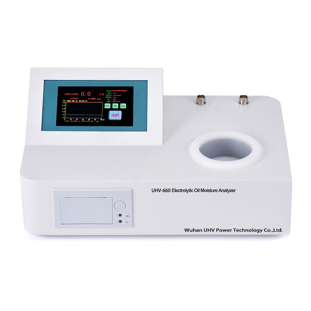
What exactly affects the "moisture" in oil products? The fully automatic micro moisture analyzer tells you the answer
2026-07-06In many key fields such as power equipment and transformer oil, the moisture content in oil is an important indicator that cannot be ignored. It not only concerns the stable operation of the equipment, but also directly affects the insulation performance and service life. What is quietly affecting the moisture in oil products? Today, let's talk about this topic and see how the fully automatic micro moisture analyzer helps us to accurately control it.The 'invisible pusher' of oil moistureThe moisture in oil products is like an 'invisible killer', and its sources can be numerous.Environmental factors: humid air and poor sealing of storage environments can both allow moisture to enter.Process: Production, filtration, injection, etc. If not properly controlled, moisture may also be introduced.Equipment itself: Long term operation of old equipment may also cause moisture infiltration due to aging seals.These seemingly tiny amounts of water, once exceeded, can have a sign
أكثر -
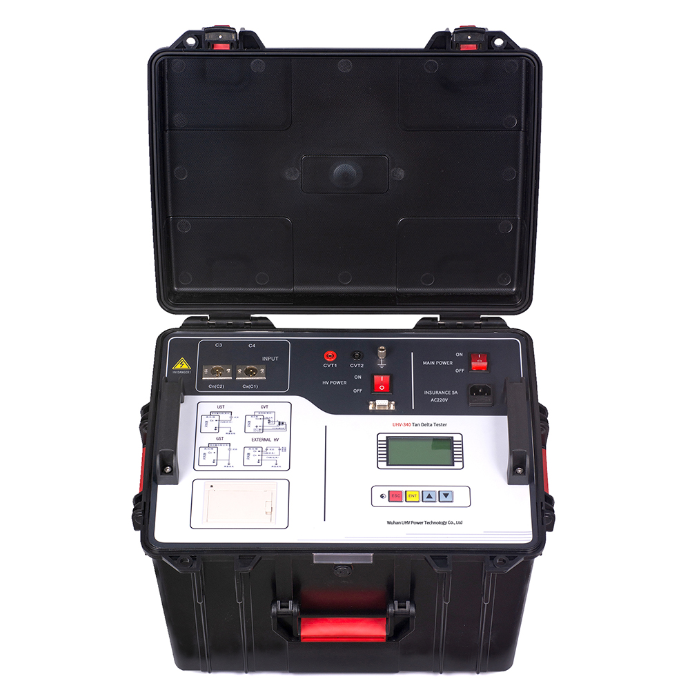
Why do we need to pay attention to automatic dielectric loss testers?
2026-07-03In the field of power equipment maintenance and quality inspection, "dielectric loss" is an unavoidable indicator. It directly reflects the performance of insulation materials and is related to the safe operation of power equipment. What does this somewhat technical term actually mean? What other factors can affect it? Today we will talk about the automatic dielectric loss tester and see what role it plays in ensuring power safety.Dielectric loss, in simple terms, refers to the phenomenon in which a dielectric converts a portion of electrical energy into thermal energy under the action of an electric field. Imagine applying a voltage to an insulating material, which is not completely leakage free. Some of the energy will be lost in the form of heat, which is known as dielectric loss. The lower the loss value, the better the insulation performance of the material, and the less likely it is to age and be damaged.There are many factors that affect dielectric loss, including:Temperature: A
أكثر -
Why pay attention to dielectric loss measuring instruments? What exactly is it measuring?
2026-07-03In the field of power equipment testing, the term "dielectric loss" may sound a bit specialized, but it is a key indicator for measuring the aging degree of insulation materials and judging the health status of equipment. Simply put, dielectric loss refers to a portion of the energy loss in an insulating medium under the action of an alternating electric field. This energy will dissipate in the form of heat, and long-term accumulation will not only affect the normal operation of the equipment, but may also lead to insulation breakdown and cause safety accidents. So, accurately measuring dielectric loss is like giving a "health check" to electrical equipment.There are many factors that can affect dielectric loss, such as temperature, humidity, electric field strength, the properties of the insulation material itself, and the service life of the equipment. For example, a humid environment can significantly increase the dielectric loss of insulation materials. As the equipment ages, the i
أكثر -
What are the safety hazards of SF6 gas micro water exceeding the standard?
2026-07-02SF6 gas, also known as sulfur hexafluoride, is a very important insulating medium in the power industry. It plays a crucial role in key power equipment such as substations. SF6 gas has high environmental requirements, among which the micro water content is a key indicator. What invisible "troubles" will SF6 gas micro water exceeding the standard bring?The importance of SF6 gas micro waterSimply put, the SF6 gas micro water tester is a "health manager" used to detect the moisture content in SF6 gas. SF6 gas itself has excellent insulation and arc extinguishing properties, but once moisture in the air enters the SF6 gas environment, the situation may become complicated. Micro water refers to the water vapor in SF6 gas that is invisible to the naked eye. Excessive micro water content, like adding blockage to SF6 gas, will greatly weaken its insulation ability and may cause a series of equipment problems.Factors affecting SF6 gas micro waterEquipment sealing: This is the most direct factor
أكثر -
SF6 qualitative leak detector: precise positioning, safeguarding power safety
2026-07-01Have you ever been troubled by the leakage of SF6 gas in power equipment? SF6 qualitative leak detector, as an indispensable "detective" in power operation and maintenance, can help us quickly identify the source of problems. It is an SF6 leak detection device that can sensitively detect small leakage points of SF6 gas.Why do SF6 gas leaks need to be detected in a timely manner?SF6 gas, also known as sulfur hexafluoride, is widely used in high-voltage switchgear due to its excellent insulation performance and arc extinguishing ability. Once a leak occurs, it will not only reduce the insulation level of the equipment and affect the stability of power supply, but also have an impact on the environment, as SF6 is a greenhouse gas. Therefore, SF6 gas leak detection is particularly important.How does SF6 qualitative leak detector work?This type of SF6 leak detection instrument usually uses technical principles such as infrared absorption or mass spectrometry. When the instrument approaches
أكثر -
Improving Power Grid Safety: How SF6 Gas Detectors Safeguard the Stable Operation of Equipment
2026-07-01SF6 gas plays a crucial role. It is widely used in high-voltage switchgear due to its excellent insulation and arc extinguishing performance. Once SF6 gas leaks, it not only affects the normal operation of equipment, but may also have an impact on the environment. Therefore, accurate and timely detection of SF6 gas has become a key link in ensuring the safety of the power grid.What is SF6 gas detection?SF6 gas, also known as sulfur hexafluoride, is a colorless, odorless, and non-toxic gas. In high-voltage electrical equipment, it is used as an insulating medium to effectively prevent electrical faults from occurring. SF6 gas detection, as the name suggests, is the use of professional instruments and equipment to monitor the concentration, density, or leakage points of SF6 gas inside the equipment. This is like conducting a "health check" on power grid equipment to ensure the stability of its internal environment.Factors affecting SF6 gas detectionEquipment sealing: This is the most dir
أكثر -
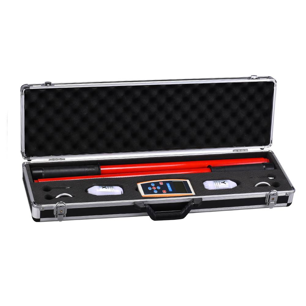
The key to improving the safety of 10kV high-voltage line operation: understanding high-voltage phase analyzer
2026-07-01In the operation and maintenance of power systems, the 10kV high‑voltage phase tester plays an essential role. It is an instrument used to check, in a de‑energised state, whether the phases of two or more high‑voltage power sources (such as incoming and outgoing lines in a substation) are consistent. Ensuring phase consistency is the fundamental safeguard against equipment damage, grid disruption, or even serious accidents caused by incorrect phase connections.Why is phase consistency so important?To put it simply, imagine wiring a three‑phase motor. If the phase sequence of the three live wires is disrupted, the motor's rotation direction will be wrong – at best it will fail to operate properly, and at worst it may burn out. In a complex 10kV high‑voltage grid, such "phase misconnection" can lead to regional blackouts, causing enormous impacts on production and daily life. Therefore, every high‑voltage line operation – especially maintenance, paralleling, and similar procedures –
أكثر


