Analysis of the Voltage Withstand Test Principle of Variable Frequency Series Resonance
This article mainly introduces the voltage withstand test principle of series resonant frequency conversion Firstly, the following components were introduced:
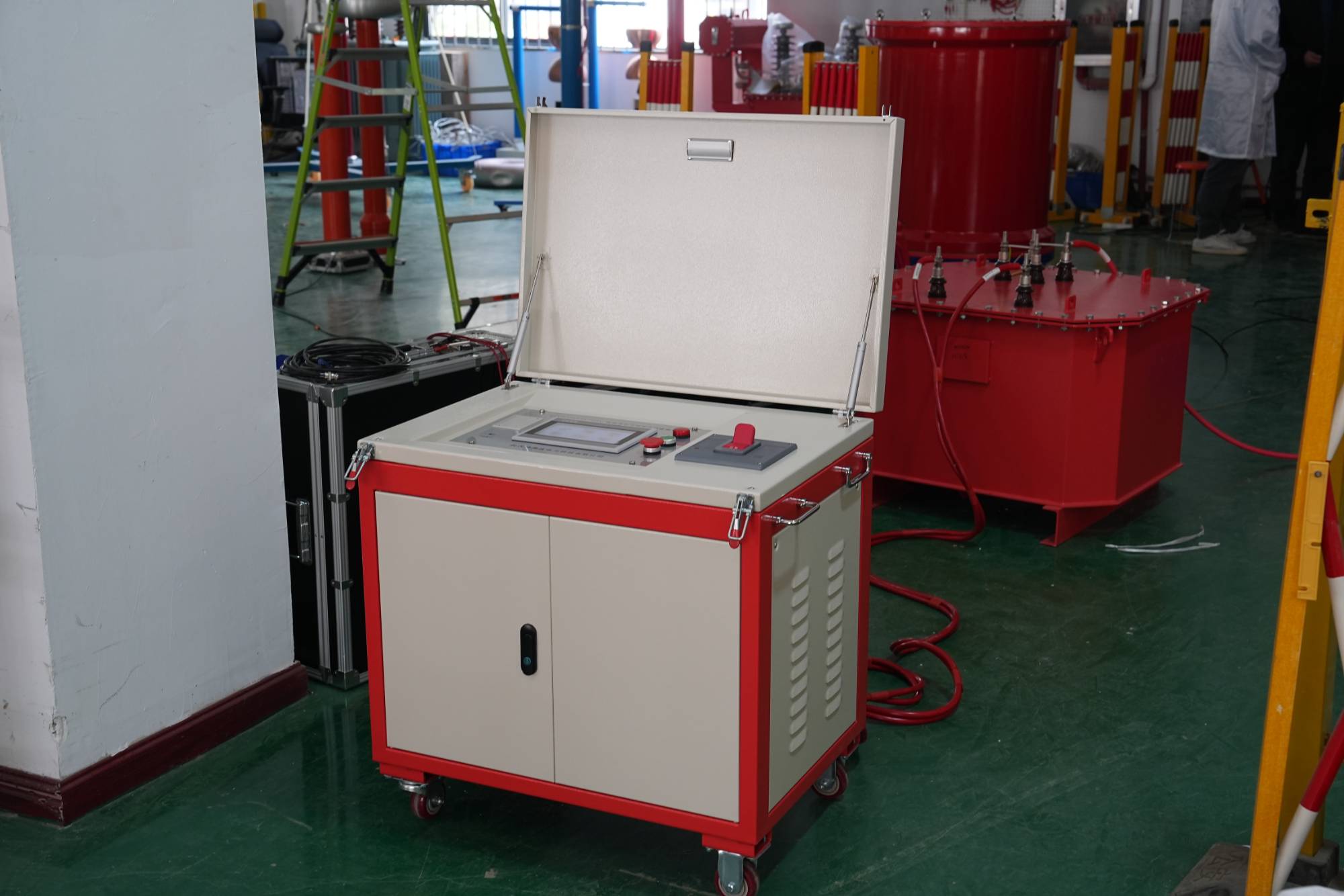
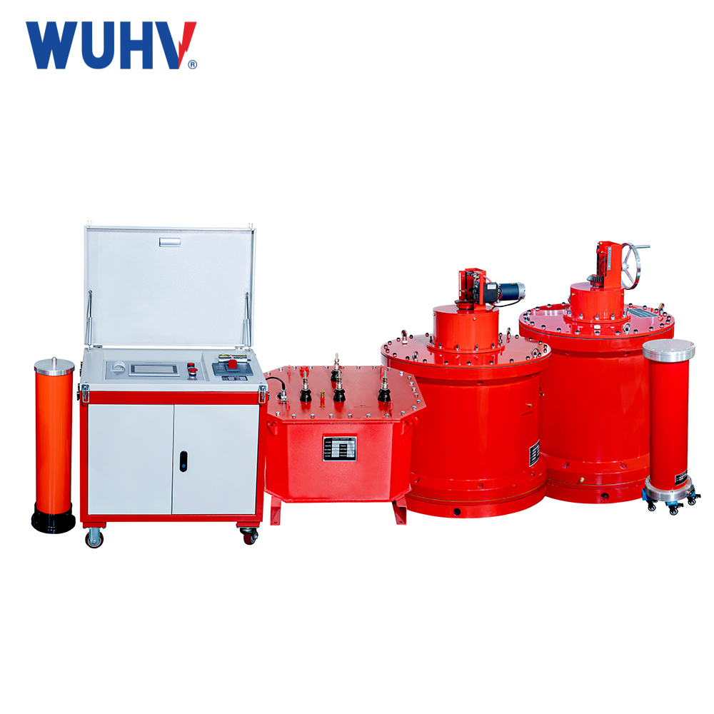
The series resonant frequency detection kit mainly consists of a frequency controller, excitation transformer, reactor, and high-voltage divider. The technology of variable frequency system controllers can be divided into two categories: desktop control environment for 20KW and above, and portable box type for 20KW and below; It can be composed of a controller and a filter.
The main function of a frequency controller is to have a fixed amplitude and adjustable amplitude and frequency sine wave with a frequency of 380V or 200V sine alternating current. And provide a power source for the development of the entire equipment. The function of the excitation transformer is to increase the output voltage of the variable frequency power supply to the appropriate test voltage Reactor L is an important component of the resonant circuit, and when the power frequency is equal to 1/(2 π√ LCX), it undergoes series resonance with the test CX.
The insulation withstand and power frequency withstand voltage of electrical engineering equipment with large capacitance through frequency conversion series resonance (such as large enterprise generator sets, power electronic transformers, power capacitors, GIS, power cables, etc.) have a certain equivalence in China within a certain working frequency range. Therefore, we provide students with the possibility to use the inductance of the frequency conversion test detection device and the capacitance of the test object in series to develop resonance voltage and conduct information exchange withstand voltage test research. Moreover, due to the low excitation voltage and light weight of the experimental design device, it is very convenient for on-site management and use by construction personnel. Explain the principle and experience of the series resonance characteristics of the testing device in practical applications.
Characteristics of frequency conversion series resonance withstand voltage test device
The principle of series resonant operation is used to generate high voltage in the circuit, usually at a frequency of 30-300Hz. The series resonant DC high-voltage generator is as follows:
Testing equipment for series resonant frequency
When the frequency (f) of the power supply, inductance (L), and capacitance (C) of the tested equipment satisfy the following equation, the circuit system is in a series resonant working state. At this time, f=1/2 π√ LC, the current in the circuit is I=Ulx/R, and the control voltage of the tested equipment is Ucx=I/ω Cx. The ratio of the output signal voltage to the excitation voltage is the quality factor of the experimental design circuit: Q=Ucx/Ulx=(ω L)/R. Due to the small resistance R in the technical test detection circuit, there is a large theoretical quality factor in the experimental operation circuit.
Generally, when up to 50 or more are normal, the output voltage is only 50 times the excitation voltage, and therefore can obtain higher testing voltage and low capacity testing with transformers. This solves the problem that the capacity of the test transformer cannot meet the requirements of different test developments in general AC withstand voltage tests.
The relationship between capacitance and inductance is ω L=1/ω c. As capacitance is inherent in testing, adjustable inductance has a high cost. Solving this problem leads to changing the resonant frequency of the power frequency circuit, adjusting the frequency of the circuit at the initial voltage, and observing the maximum change in Uc. When the frequency increases or decreases, the resonant voltage decreases. When the voltage is the resonant point voltage, the resonant frequency is the resonant frequency. In addition, since the testing circuit is in a resonant state, the circuit itself has good filtering effect, and the waveform of high-order harmonic components is greatly reduced in both devices to output a good sine wave waveform.
When the test sample discharges or breaks down, that is, the medium value capacitor in the circuit is short circuited, the resonance technical conditions are destroyed, the voltage can significantly decrease, and the recovery working voltage continues to rise slowly. There is no transient overvoltage on the test sample, and the short-circuit current supplied by the power supply product will be limited by the reactance and reduced, thus limiting the severity of damage to the test equipment.


