Series resonance (also known as variable frequency resonance) compensation - a capacitor connected in series with the line can control the effective reactance between the two ends of the line. The effective reactance is given by the following equation
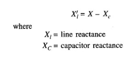
It is obvious that capacitors will reduce the effective line reactance. This leads to improvements in system performance as follows.
(i) The voltage drop in the circuit is reduced (compensated), that is, the terminal voltage change is minimized.
(ii) Prevent voltage collapse.
(iii) Steady state power transmission increases; It is inversely proportional to X'l.
(iv) Due to the increase in transient stability limit.
The advantages and problems of series capacitor compensators are related. Capacitor reactance X c forms a series resonant circuit with the total series reactance

The oscillation natural frequency of this circuit is
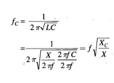
F=system frequency
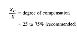
For this level of compensation
This is subharmonic oscillation.
Although series resonant compensation is generally found to be cost-effective compared to parallel compensation, sustained oscillations below the fundamental system frequency can cause this phenomenon, known as subsynchronous resonance (SSR), which was first observed in 1937 but attracted worldwide attention only in the 1970s after two turbine generator shaft failures at the Majave power plant in southern Nevada. Theoretical research suggests that the interaction between the series capacitor compensation line oscillating at subharmonic frequencies and the torsional mechanical oscillation of the turbine generator set can result in negative damping, thereby enhancing the two oscillations. Subsynchronous resonance is usually not the main issue, and low-cost measures and protective measures can be adopted.
By using a sensitive relay to detect low subharmonic currents on the circuit, the relay will trigger the action of bypassing the series capacitor at a certain current level.
Adjust the excitation current of the generator to provide enhanced positive damping at subharmonic frequencies.
Under light load conditions, it is necessary to use series inductors for line compensation to counteract excessive voltage rise (Faraday effect).
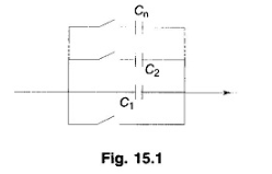
As the load on the line and especially the reactive power on the line change, it is necessary to adjust the compensation according to the acceptable voltage curve. The mechanical switch device used to adjust the capacitance of the capacitor bank connected in series with the circuit is shown in Figure 15.1. By disconnecting the switches of each capacitor through the capacitor C1 activated by the bypass switch, the capacitance can be changed. This is a gradual arrangement. In any emergency situation, the start switch can also bypass the entire group. Due to the current carrying nature of the switch connected in series with the capacitor, a suitable circuit breaker is required. However, in recent days, it is usually avoided to use series connected circuit breakers to switch capacitors, which are fixed or thyristor switched.
With the rapid development of thyristor devices and related switch control technologies, the capacitance of series capacitor groups can be more effectively controlled. Gradually and steadily control. This is demonstrated by the schematic diagram in Figure 15.2, where the capacitor is connected in parallel by two thyristors. When triggering a thyristor, one thyristor alternately carries current in the positive half cycle, while the other carries current in the negative half cycle.
During each half cycle when the thyristor is triggered (at an adjustable angle), it will conduct current for the remaining time of the half cycle until the natural current reaches zero. The turn off time of the thyristor current is determined by the capacitor and the capacitor voltage, which is denoted as νÇ. During the conduction time, the short circuit of the thyristor capacitor is denoted as ν C ^=0, and the current flows through the thyristor. Repeat the same process in the other half of the cycle. This means that ν Ç can control for any given I, which is equivalent to reducing the capacitance to C by=ν Ç/I. Through this scheme, the capacitance can be smoothly controlled by adjusting the trigger angle.
Nowadays, thyristors can be used to carry high currents and withstand high voltages encountered in power systems during downtime. The latest device called Gate Turn Off (GTO) thyristor has the ability to simultaneously turn on and off the angle (time) through an appropriate triggering circuit.
This means a larger range and finer control over capacitors. Similarly, series reactors in pipelines can be controlled.
All controlled and uncontrolled (fixed) series resonant compensators require protective devices. Protection can be provided externally through lightning arresters, other voltage limiting devices, or similar bypass switch devices. Under no circumstances should it exceed the VI level of the thyristor.
Depending on (i) the type of solid-state device used, (ii) capacitor and/or reactor compensation, and (iii) switch (stepwise) or smooth (stepless) control, several compensation schemes have been designed and used. Some more common compensation schemes are as follows.
Thyristor controlled series capacitor (TCSC)
Thyristor switch series capacitor (TSSC)
Thyristor controlled reactor with fixed capacitor (TCR+FC)
GTO thyristor controlled series capacitor (GCSC)
Thyristor controlled reactor (TCR)
Capacitor and/or reactor series resonant compensator is used to modify the impedance of the line. An alternative method is to introduce a controllable voltage source in series with the circuit. This scheme is called Static Synchronous Series Resonant Compensator (SSSC). SSSC can sense capacitive and inductive voltages in series with the line, thereby expanding the working range of the scheme. It can be used for power flow control to increase or decrease reactive power flow on the line. In addition, this scheme has better stability and is more effective in suppressing electromechanical oscillations.
Although various types of compensators can provide efficient power flow control, their working characteristics and compensation functions vary. These differences are related to the inherent properties of their control circuits. And they exhibit different loss characteristics.
From the perspective of almost maintenance free operation, impedance modification schemes (capacitors and/or reactors) are more outstanding. The specific type of compensator used largely depends on the specific application.


