When the series combination of the inductance of the facility transformer and the parallel capacitor group in the facility resonates at the harmonic frequency injected from the distribution system, series resonance occurs. In this case, the facility itself may not be an important harmonic current generator, but due to the series LC combination "absorbing" important harmonic currents from the upstream distribution system, the equipment may still encounter resonant harmonic effects. Here is an example of a system that may experience series resonance.
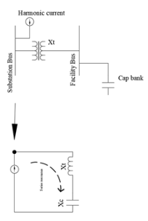
The voltage across the capacitor is amplified and distorted, which can be expressed as:

Among them, Vh is the harmonic voltage present in the system. R is the inherent series resistance of the circuit above, not shown in the diagram. Note that the resonance values of Xt and Xc are equal and opposite in magnitude, thus canceling each other out.
Application of Series and Parallel Resonance in Actual Power Systems
In fact, due to the circuit topology, series resonance (also known as variable frequency resonance) conditions will also have parallel resonance conditions. In the following figure, Xt is the reactance of the facility transformer, and Xc is the reactance of the facility capacitor bank. The source reactance is given by Xs.
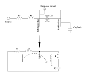
The first series resonance point of the system is determined by Xc and Xt, while the first parallel resonance point is determined by Xc, Xt, and Xs.
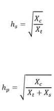
From the equations of series resonance and parallel resonance, it can be seen that in actual power system installation, the parallel resonance point is always lower than the series resonance point.
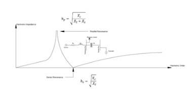
The difference between series resonance and parallel resonance in power systems is that series resonance produces low impedance (absorbing maximum current into the system), while parallel resonance produces high impedance. Even with small currents, it can cause large harmonic voltage drops, resulting in voltage stress-related damage.


